This topic includes:
▪Art-Net Remote Troubleshooting
MADRIX 5 can receive incoming data or can be controlled remotely [DMX Input].
That means you can use another controller or device:
▪to send data to the software and use this data [e.g., for Scripts, Macros, or tests],
▪to send commands to the software [Remote Control],
▪to route incoming data onto your output [also known as Mapping/Merging/DMX-Thru],
▪to trigger MADRIX 5 TRI Effects.
In general, 3 options are available to you:
▪DMX-IN
[Receiving DMX input data.]
▪Art-Net Remote
[Receiving Art-Net data.]
▪sACN Input
[Receiving Streaming ACN data.]
Step-By-Step Configuration
1] Enable drivers for your MADRIX DMX device.
2] Activate your DMX device.
3] Enable DMX-IN.
4] Choose how to use incoming signals.
1] Enable Drivers For Your DMX Device
▪Go to the menu Preferences > Options... > Devices USB
[Keyboard shortcut: Ctrl+Alt+O > Devices USB]
▪A new window will open.
▪By default, the drivers for all MADRIX devices should be activated by default.
▪If not, activate the appropriate driver. Learn more »Devices USB
2] Activate Your DMX Device
▪Go to the menu Preferences > Device Manager... > DMX Devices
[Keyboard shortcut: F4]
▪A new window will open.
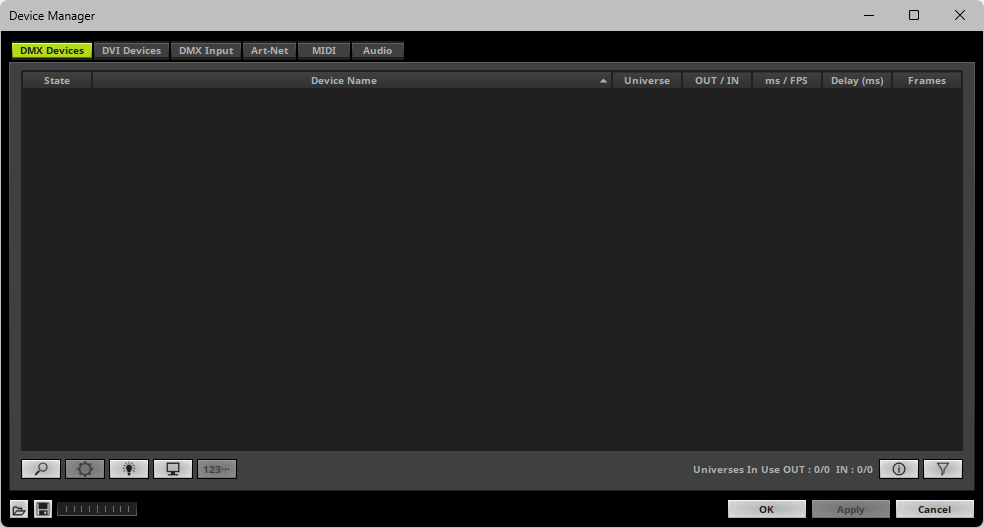
▪MADRIX 5 may have already found your connected DMX devices. They will be shown in the list.
▪Click ![]() if your DMX devices are not shown in the list.
if your DMX devices are not shown in the list.
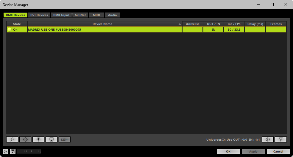
▪ Select your DMX device in the list.
▪Right Mouse Click or Left Mouse Double-Click on the column State to set from Off to On [indicated by green light].
▪Right Mouse Click or Left Mouse Double-Click on the column OUT / IN to set to IN for data input.
3] Enable DMX-IN
▪Go to the menu Preferences > Device Manager... > DMX Input
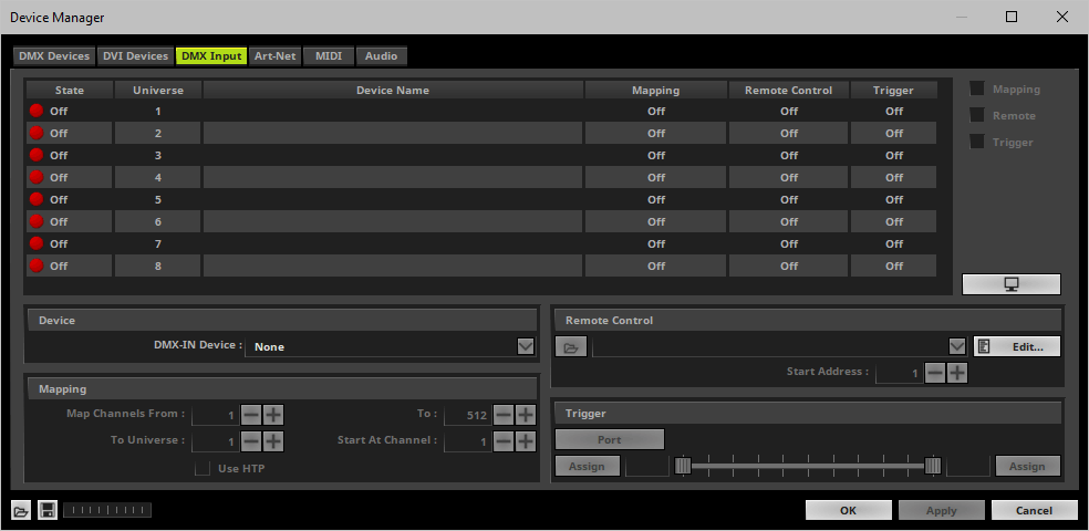
▪Select your preferred DMX Universe in the list.
[By default, universe 1 to 8 are listed. If you wish to increase the number of input universes, you can change the setting. Learn more »Performance]
▪Choose your Device in the section Device
- You can also use it as a search field. Enter a value or name to search for it.
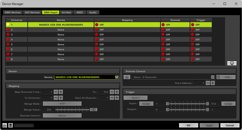
▪[If needed, you can disable DMX-IN by choosing None for your Device in the section Device]
▪[If needed, you can choose one, single source to map them to multiple virtual DMX-input universes via Mapping]
4] Choose How To Use Incoming Signals
Data
▪At this point, MADRIX 5 is already receiving any incoming data.
▪You can now use this data, for example for Scripts and Macros. Learn more »Macros And Scripts
▪If you want to monitor incoming signals, select your DMX universe/DMX device in the list and click 
Learn more »Tools
▪Use Mapping, if you want to route incoming DMX signals through MADRIX 5 to your output [Mapping/Merging/DMX-Thru].
▪First, select your device in the list.
▪Right Mouse Click or Left Mouse Double-Click on the column Mapping to set from Off to On [indicated by green light 
 ].
].
▪This feature maps incoming data to the specified DMX universe and channels.
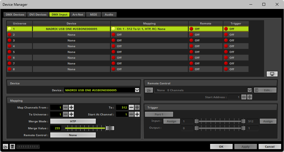
▪Configure the following settings in the section Mapping
- Map Channels From - Defines which incoming channels are used. This is the start channel to specify the range of channels.
- To - Defines which incoming channels are used. This is the end channel to specify the range of channels.
- To Universe - Defines onto which DMX output universe the specified range of incoming channels should be mapped.
[When mapping several DMX Input Universes/input devices to the same Universe, data will be processed one universe after another and the second DMX Input Universe is being mapped onto the result of the first DMX Input Universe, and so on.]
- Start At Channel - Defines the first DMX channel of the DMX output universe that should be used.
▪Merge Mode - You can map incoming data to a DMX address range that MADRIX 5 already controls. When merging data, the potential DMX output of MADRIX 5 is merged onto the incoming signal.
Merge Mode defines how that DMX output universe is merged onto the incoming data. Choose from the options below as the best choice depends on your usage scenario. The default setting is HTP.
[Merge Value, see below, defines how much data is merged. Merge Mode and Merge Value can be controlled via Remote Control]
- Input Only - Disables the merging of data. Solely the incoming signal will be mapped onto the DMX output universe. Merge Value is thus not available for this mode.
- HTP - Is short for Highest Takes Precedence. MADRIX 5 will compare incoming values with the potential DMX output. As a result, only the highest of both values on a particular channel will be sent to the output.
- LoTP - Is short for Lowest Takes Precedence. Is the opposite of HTP. MADRIX 5 will compare incoming values with the potential DMX output. As a result, only the lowest of both values on a particular channel will be sent to the output.
- Multiply - Incoming values will be multiplied with the potential DMX output, and then sent to output. [Values are converted to always ensure a maximum value of 255.]
- Multiply, Inverted - Incoming values will be multiplied with the potential DMX output, but the result will be inverted [low results will become high results and vice versa] before being sent to output. [Values are converted to always ensure a maximum value of 255.]
- Add - Incoming values will be added to the potential DMX output, and then sent to output.
- Subtract - Incoming values will be subtracted from the potential DMX output, and then sent to output.
- Subtract, Reversed - The potential DMX output will be subtracted from the incoming values, and then sent to output.
- XF - Is short for Cross-Fade. See also »Crossfader
- WF - Is short for White-Fade. See also »Crossfader
- MADRIX 5 Only - Does not factor in any incoming values and only the potential DMX output is sent to output. Merge Value is thus not available for this mode.
▪Merge Value - Defines how much of the potential DMX output is merged onto the incoming signal. A value of 0 means that no data from MADRIX 5 is merged onto the incoming signal, and thus only the incoming signal is mapped onto the universe. The default setting is 255. [Merge Mode and Merge Value can be controlled via Remote Control]
- XF and WF will have the same result as a fade from the crossfader. At 255, only the MADRIX 5 data is sent to output. See also »Crossfader
- All other Merge Modes behave like the Opacity value of a layer, whereas the upper layer is the MADRIX 5 data and the base layer is the incoming signal. See also »Layers
▪Remote Control - Allows you to assign a port to the DMX Input Universe for Remote Control
- Up to 8 ports can be assigned.
- You can then assign a DMX remote-control channel to this port in the »DMX-IN Remote Editor
- As such, you may assign a single port to a single DMX Input Universe/input device or you may assign the same port to several DMX Input Universes/input devices, thereby controlling several different input merges with a single DMX channel.
- Each port remembers the settings for Merge Mode and Merge Value.
- When assigning several DMX Input Universes/input devices to the same port, the settings for Merge Mode and Merge Value will be synchronized across all of them.
- The default setting is None, which disables the option for remote control.
▪Use Remote Control, if you want to control the MADRIX 5 Software remotely
▪First, select your device in the list.
▪Right Mouse Click or Left Mouse Double-Click on the column Remote to set from Off to On [indicated by green light 
 ].
].
▪Select one of the built-in protocols in the section Remote Control as explained below
or create your own remote configuration.
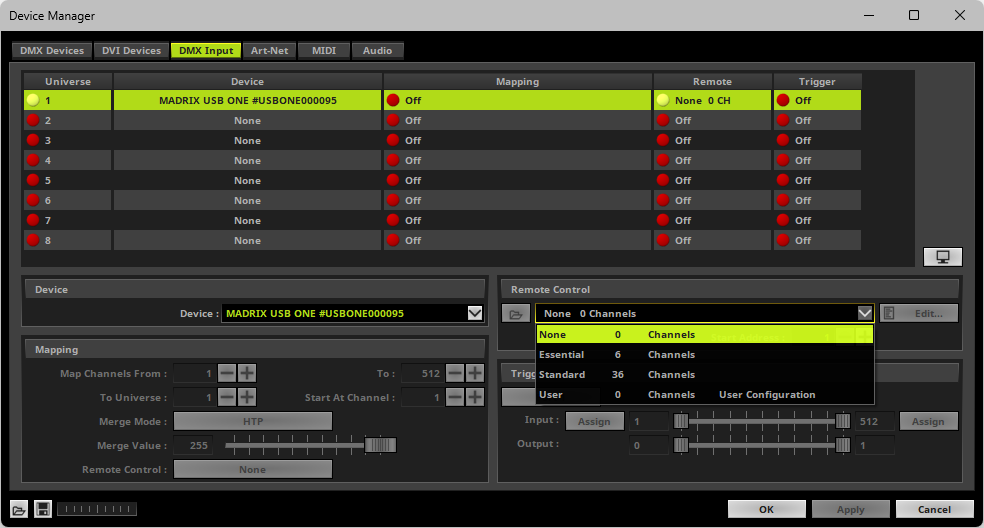
|
Open - Loads a previously saved MADRIX 5 DMX Remote Configuration file [of the file type *.mdrx]. |
|
Protocols - Choose from a pre-configured protocol [configuration]. |
|
DMX-IN Remote Editor - Allows you to modify a configuration or create a new configuration. |
|
Start Address - Defines on which particular DMX channel the protocol should start. The whole protocol will be mapped to this new address area. |
Trigger
▪Use Trigger, if you want to use incoming signals for the MADRIX 5 TRI Effects.
▪First, select your device in the list.
▪Right Mouse Click or Left Mouse Double-Click on the column Trigger to set from Off to On [indicated by green light 
 ].
].
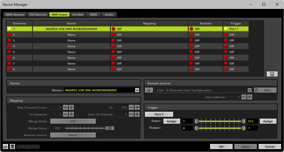
|
Port - Assigns a trigger port [Port 1 - 64] to this DMX-IN Device. MADRIX 5 allows you to send trigger signals from up to 64 different devices [64 ports] and assign a MADRIX 5 TRI Effect to the corresponding port. |
|
Input Value Range - Defines the DMX channels that are used for the trigger signal. [Incoming DMX values then usually determine the intensity of the effect.] |
|
Assign Minimum Value - Automatically assigns the minimum DMX channel when using the controller. |
|
Assign Maximum Value - Automatically assigns the maximum DMX channel when using the controller. |
|
Output Value Range - Defines how the input is mapped to the MADRIX 5 Effect. |
Learn more »[TRI] Trigger Effects
Overview
An Art-Net device can be used for DMX input as well. This feature is called Art-Net Remote.
Step-By-Step Configuration
1] Set up network settings in Windows.
2] Activate Art-Net and create an input device.
3] Create an Art-Net input device.
4] Enable DMX-IN.
5] Choose how to use incoming signals.
1] Set Up Network Settings In Windows
Art-Net is used to send DMX512 data over Ethernet network. Because of this, you need to configure the settings of your network card in Windows first.
▪Configure your network card in Windows.
▪Use an IP address from the following address range:
2.0.0.1 ... 2.255.255.254
or
10.0.0.1 ... 10.255.255.254
▪Use the following Subnet mask
255.0.0.0
▪Learn more »Tips [Microsoft Windows / Networks / USB]
You must use this address area! Art-Net may not work otherwise.
2] Activate Art-Net And Create An Input Device
▪Go to the menu Preferences > Device Manager... > Art-Net
[Keyboard shortcut: F4 > Art-Net]
▪A new window will open.
▪Activate the checkbox Enable [in the upper, right corner].
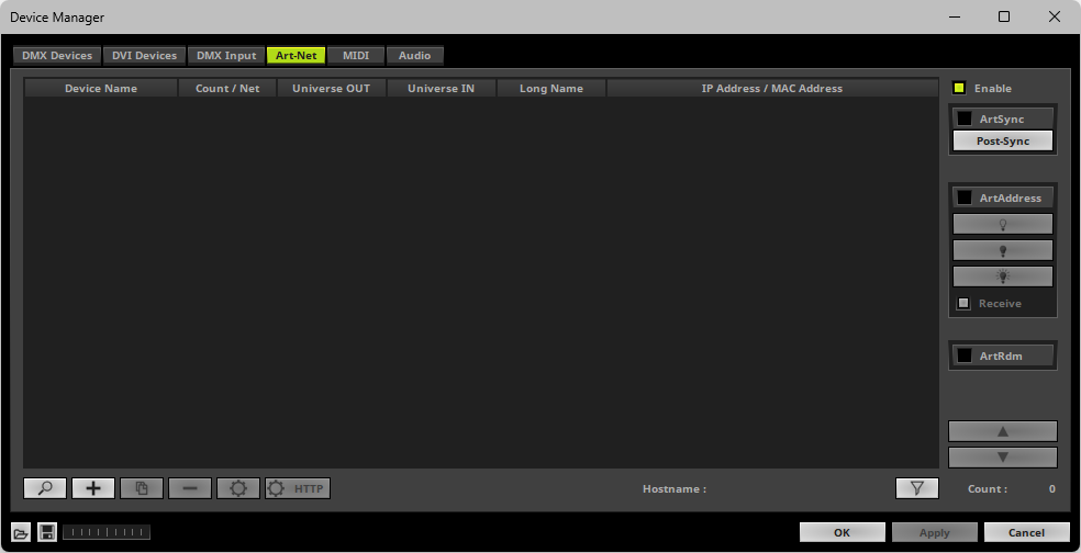
▪Click ![]()
▪A new window will open.
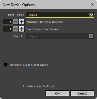
▪Port Type - Choose Input
▪Number Of New Devices - Enter the number of devices you wish to add. [1 is often enough and thus recommended.]
▪Port Count Per Device - Enter the number of ports each newly created device should have. Per device a maximum number of 4 ports is available. [1 is often enough and thus recommended.]
▪Receive Via Unicast Mode - Activates Unicast Mode for all newly created input devices.
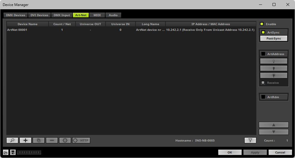
▪Select the input device in the list.
▪Click ![]()
▪A new window will open.
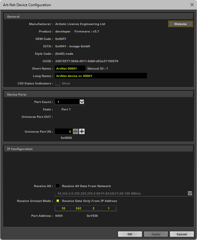
▪Configure the following settings:
▪Port Count - Defines how many DMX universes can be received by MADRIX 5. You can choose 1, 2, 3, or 4.
[MADRIX 5 can receive a maximum of 4 universes regarding Art-Net Remote.]
▪Universe Port IN - Defines from which DMX universe MADRIX 5 receives the data.
- Choose the universe on which your Art-Net device is sending the data!
▪Receive All - If activated, MADRIX 5 can receive data from the selected network.
- Any Art-Net device, such as an lighting desk, can send data to MADRIX 5.
- Select the correct network first.
- Receives limited broadcast, directed broadcast, and unicast.
▪Receive Unicast Mode - If activated, MADRIX 5 will only receive data from the specified IP address. [This is the recommended setting.]
IP Address - Needs to be set up if Unicast Mode is activated.
- Enter the IP address of the device that is sending data to MADRIX 5. Do not enter the IP address of the PC that is running the MADRIX 5 Software!
▪Click Apply to confirm.
▪Click OK to close the window.
3] Activate The Art-Net Input Device
▪Go to the menu Preferences > Device Manager... > DMX Devices
▪Your ArtNet input device will be shown in the list.
[If the Port Count above is set to 2, 3, or 4, you will see up to 4 devices in the list.]
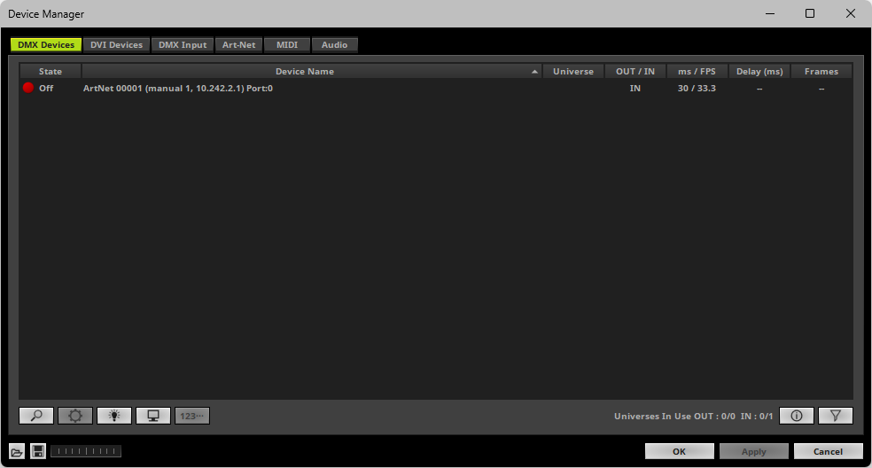
▪Select your devices in the list.
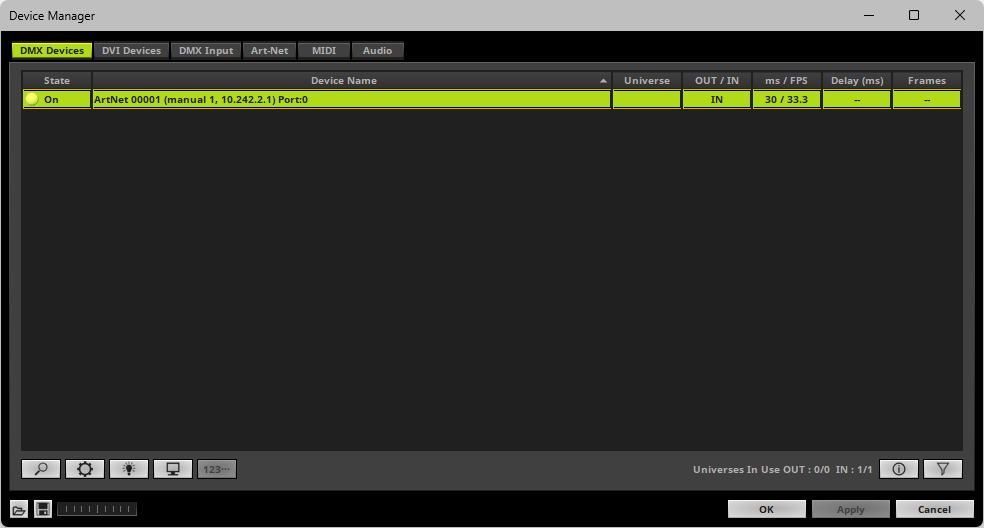
▪Right Mouse Click on the column State to set from Off to On [indicated by green light].
[IN is automatically activated.]
▪If needed, adjust the frame time to increase or decrease the frame rate.
- Right Mouse Click on the column ms / FPS and enter the required number.
4] Enable DMX-IN
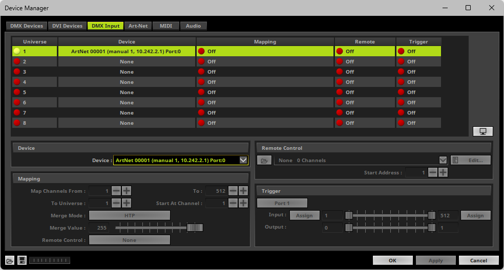
▪Go to the menu Preferences > Device Manager... > DMX Input

▪Select your preferred DMX Universe in the list.
[By default, universe 1 to 8 are listed. If you wish to increase the number of input universes, you can change the setting. Learn more »Performance]
▪Choose your Device in the section Device by choosing the Art-Net input device via its IP address.
- You can also use it as a search field. Enter a value or name to search for it.
▪[If needed, you can disable DMX-IN by choosing None for your Device in the section Device]
▪[If needed, you can choose one, single source to map them to multiple virtual DMX-input universes via Mapping]
5] Choose How To Use Incoming Signals
Data
▪At this point, MADRIX 5 is now already receiving any incoming data.
▪You can now use this data, for example for Scripts and Macros. Learn more »Macros And Scripts
▪If you want to monitor incoming signals, select your DMX universe/DMX device in the list and click 
Learn more »Tools
▪Use Mapping, if you want to route incoming DMX signals through MADRIX 5 to your output [Mapping/Merging/DMX-Thru].
▪First, select your device in the list.
▪Right Mouse Click or Left Mouse Double-Click on the column Mapping to set from Off to On [indicated by green light 
 ].
].
▪This feature maps incoming data to the specified DMX universe and channels.
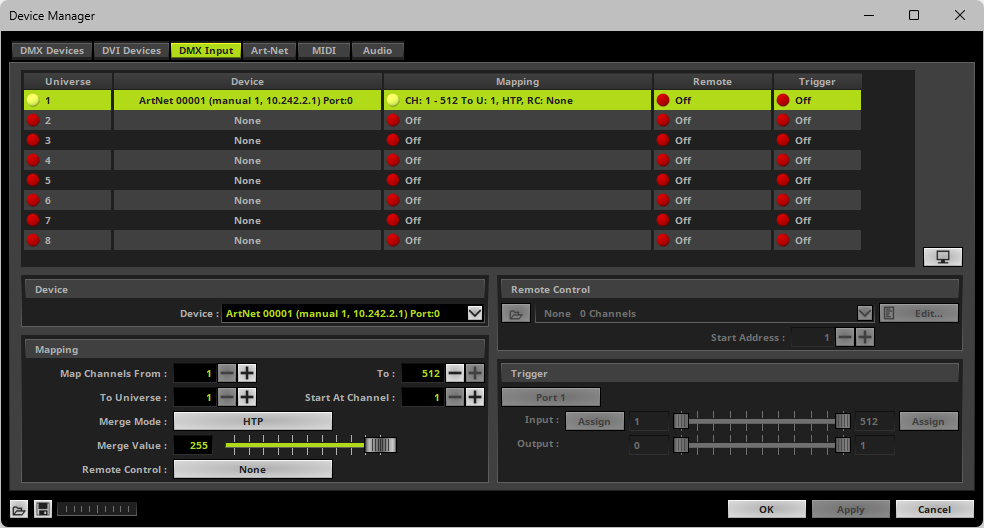
▪Configure the following settings in the section Mapping
- Map Channels From - Defines which incoming channels are used. This is the start channel to specify the range of channels.
- To - Defines which incoming channels are used. This is the end channel to specify the range of channels.
- To Universe - Defines onto which DMX output universe the specified range of incoming channels should be mapped.
[When mapping several DMX Input Universes/input devices to the same Universe, data will be processed one universe after another and the second DMX Input Universe is being mapped onto the result of the first DMX Input Universe, and so on.]
- Start At Channel - Defines the first DMX channel of the DMX output universe that should be used.
▪Merge Mode - You can map incoming data to a DMX address range that MADRIX 5 already controls. When merging data, the potential DMX output of MADRIX 5 is merged onto the incoming signal.
Merge Mode defines how that DMX output universe is merged onto the incoming data. Choose from the options below as the best choice depends on your usage scenario. The default setting is HTP.
[Merge Value, see below, defines how much data is merged. Merge Mode and Merge Value can be controlled via Remote Control]
- Input Only - Disables the merging of data. Solely the incoming signal will be mapped onto the DMX output universe. Merge Value is thus not available for this mode.
- HTP - Is short for Highest Takes Precedence. MADRIX 5 will compare incoming values with the potential DMX output. As a result, only the highest of both values on a particular channel will be sent to the output.
- LoTP - Is short for Lowest Takes Precedence. Is the opposite of HTP. MADRIX 5 will compare incoming values with the potential DMX output. As a result, only the lowest of both values on a particular channel will be sent to the output.
- Multiply - Incoming values will be multiplied with the potential DMX output, and then sent to output. [Values are converted to always ensure a maximum value of 255.]
- Multiply, Inverted - Incoming values will be multiplied with the potential DMX output, but the result will be inverted [low results will become high results and vice versa] before being sent to output. [Values are converted to always ensure a maximum value of 255.]
- Add - Incoming values will be added to the potential DMX output, and then sent to output.
- Subtract - Incoming values will be subtracted from the potential DMX output, and then sent to output.
- Subtract, Reversed - The potential DMX output will be subtracted from the incoming values, and then sent to output.
- XF - Is short for Cross-Fade. See also »Crossfader
- WF - Is short for White-Fade. See also »Crossfader
- MADRIX 5 Only - Does not factor in any incoming values and only the potential DMX output is sent to output. Merge Value is thus not available for this mode.
▪Merge Value - Defines how much of the potential DMX output is merged onto the incoming signal. A value of 0 means that no data from MADRIX 5 is merged onto the incoming signal, and thus only the incoming signal is mapped onto the universe. The default setting is 255. [Merge Mode and Merge Value can be controlled via Remote Control]
- XF and WF will have the same result as a fade from the crossfader. At 255, only the MADRIX 5 data is sent to output. See also »Crossfader
- All other Merge Modes behave like the Opacity value of a layer, whereas the upper layer is the MADRIX 5 data and the base layer is the incoming signal. See also »Layers
▪Remote Control - Allows you to assign a port to the DMX Input Universe for Remote Control
- Up to 8 ports can be assigned.
- You can then assign a DMX remote-control channel to this port in the »DMX-IN Remote Editor
- As such, you may assign a single port to a single DMX Input Universe/input device or you may assign the same port to several DMX Input Universes/input devices, thereby controlling several different input merges with a single DMX channel.
- Each port remembers the settings for Merge Mode and Merge Value.
- When assigning several DMX Input Universes/input devices to the same port, the settings for Merge Mode and Merge Value will be synchronized across all of them.
- The default setting is None, which disables the option for remote control.
▪Use Remote Control, if you want to control the MADRIX 5 Software remotely
▪First, select your device in the list.
▪Right Mouse Click or Left Mouse Double-Click on the column Remote to set from Off to On [indicated by green light 
 ].
].
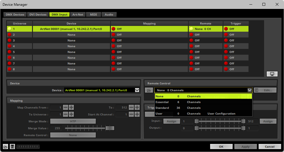
▪Select one of the built-in protocols in the section Remote Control as explained below
or create your own remote configuration.
|
Open - Loads a previously saved MADRIX 5 DMX Remote Configuration file [of the file type *.mdrx]. |
|
Protocols - Choose from a pre-configured protocol [configuration]. |
|
DMX-IN Remote Editor - Allows you to modify a configuration or create a new configuration. |
|
Start Address - Defines on which particular DMX channel the protocol should start. The whole protocol will be mapped to this new address area. |
Trigger
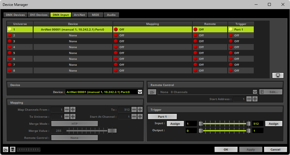
▪Use Trigger, if you want to use incoming signals for the MADRIX 5 TRI Effects.
▪First, select your device in the list.
▪Activate Trigger
|
Port - Assigns a trigger port [Port 1 - 64] to this DMX-IN Device. MADRIX 5 allows you to send trigger signals from up to 64 different devices [64 ports] and assign a MADRIX 5 TRI Effect to the corresponding port. |
|
Input Value Range - Defines the DMX channels that are used for the trigger signal. [Incoming DMX values then usually determine the intensity of the effect.] |
|
Assign Minimum Value - Automatically assigns the minimum DMX channel when using the controller. |
|
Assign Maximum Value - Automatically assigns the maximum DMX channel when using the controller. |
|
Output Value Range - Defines how the input is mapped to the MADRIX 5 Effect. |
Learn more »[TRI] Trigger Effects
Art-Net Remote Troubleshooting
If you are encountering problems, please work through the following checklist:
▪Double-check the settings of your network card.
▪Make sure to set up the Windows Firewall correctly. Learn more »Tips [Microsoft Windows / Networks / USB]
▪Double-check the settings of the ArtNet Remote device in MADRIX 5.
▪Use the DMX Watcher to monitor incoming data.
Overview
Streaming ACN devices can be used for DMX input as well.
1] Windows Network Settings
▪MADRIX 5 automatically sets up Streaming ACN network settings for you.
▪You only need a computer with a network card and a valid IP address.
▪You do not have to change the IP address settings in Windows for Streaming ACN!
▪The IP address range for sACN devices is 239.255.X.X according to the Streaming ACN specifications.
[Even if your sACN devices are set to a different IP address range, you may try the connection from MADRIX 5 to your devices.]
▪Make sure that your Firewall does not block data of the 239.255.X.X IP address range!
▪Check the settings of the Windows Firewall.
▪Learn more »Tips [Microsoft Windows / Networks / USB]
2] Activating Streaming ACN
▪Go to the menu Preferences > Options... > Devices Network
[Keyboard shortcut: Ctrl+Alt+O > Devices Network]
▪Activate ESTA - Streaming ACN
▪Choose your network card from the drop-down list. Make sure to select the correct network adapter that will be used for Streaming ACN!
[The IP address and Subnet mask label should help you select the correct adapter. It is not necessary to change any of these networks settings.]
▪ACN Device Count - Set up how many you are going to use.
[This is the total amount of OUT and IN devices. Please set the exact number of devices you are using. If the count is higher, this creates unnecessary network traffic.]
▪Click Apply
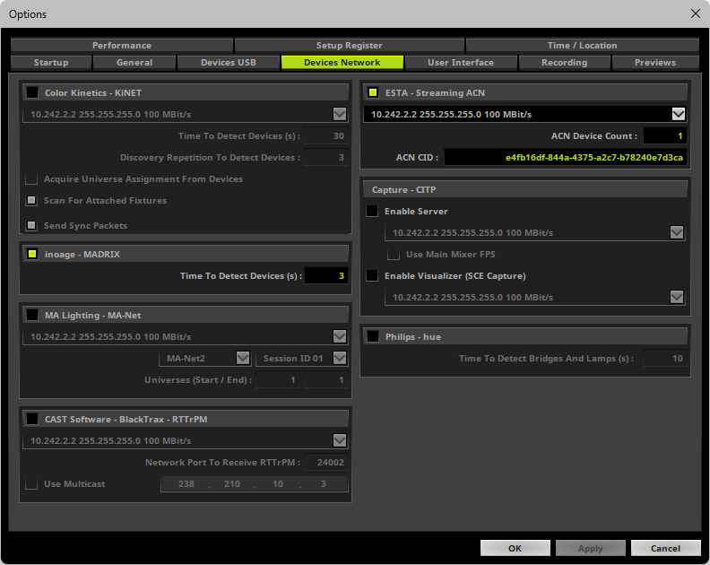
▪ACN CID - Being a network protocol, Streaming ACN sends a so-called CIDs [Component Identifier].
- Every single ACN device has such a unique ID.
- When using Streaming ACN, your MADRIX 5 Software is one of those devices.
- When you start MADRIX 5 for the first time, this ID will be generated automatically for you. From this point onwards it will be used on your PC.
- With this ID your MADRIX 5 Software can be easily identified in the network. Interfaces can detect this unique ID and can be configured to receive data from this particular device. Please note that the ACN interface must support this feature.
- Do not change the ACN CID, unless you are an experienced user!
▪Click OK to close the window.
3] Enabling Input
▪Go to Preferences > Device Manager... > DMX Devices
[Keyboard shortcut: F4]
▪MADRIX 5 automatically creates and adds the number of interfaces to the list.
[according to ACN Device Count]
▪Select your device.
▪Set to OUT / IN to IN if you wish to receive incoming data through this device.
▪Set State Off to State ON
▪Click Apply
▪In DMX-IN mode, you will not be able to select the ACN protocol. MADRIX 5 will automatically select the correct protocol version.
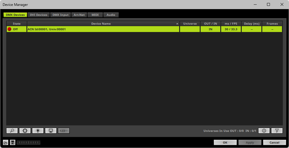
▪Note: If you are loading a MADRIX 5 Setup, please check if the number of ACN devices in your setup corresponds with the number that is activated. The Setup stores the number of devices. But if you changed the amount and then loaded the Setup, the newly defined number will be activated.
4] Configure Your Device
▪Make sure that your device is still selected under Preferences > Device Manager... > DMX Devices
▪Click ![]()
▪A new window will open.
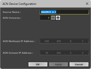
Set up the following settings for your devices:
▪Source Name - Allows you to set up a specific name for the device. This name is send via network as well. Therefore, interfaces may be able to retrieve this name and can be configured to receive data from this source.
- If you are using the default name MADRIX U:X, the universe will automatically be displayed in the name [represented by X: 1, 2, 3, etc.].
▪ACN Universe - Defines the DMX universe from which data is received.
- Set up the same universe that is set up in your sACN device.
- According to the Streaming ACN specifications, MADRIX 5 will automatically change the ACN IP Address according to the ACN Universe.
▪Click Apply to confirm your changes.
▪Click OK to close the window.
5] Enable DMX-IN
▪Go to the menu Preferences > Device Manager... > DMX Input

▪Select your preferred DMX Universe in the list.
[By default, universe 1 to 8 are listed. If you wish to increase the number of input universes, you can change the setting. Learn more »Performance]
▪Choose your Device in the section Device
- You can also use it as a search field. Enter a value or name to search for it.
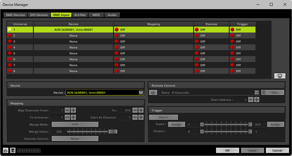
▪[If needed, you can disable DMX-IN by choosing None for your DMX-IN Device in the section Device]
▪[If needed, you can choose one, single source to map them to multiple virtual DMX input universes via Mapping]
6] Choose How To Use Incoming Signals
Data
▪At this point, MADRIX 5 is now already receiving any incoming data.
▪You can now use this data, for example for Scripts and Macros. Learn more »Macros And Scripts
▪If you want to monitor incoming signals, select your DMX universe/DMX device in the list and click 
Learn more »Tools
▪Use Mapping, if you want to route incoming DMX signals through MADRIX 5 to your output [Mapping/Merging/DMX-Thru].
▪First, select your device in the list.
▪Right Mouse Click or Left Mouse Double-Click on the column Mapping to set from Off to On [indicated by green light 
 ].
].
▪This feature maps incoming data to the specified DMX universe and channels.
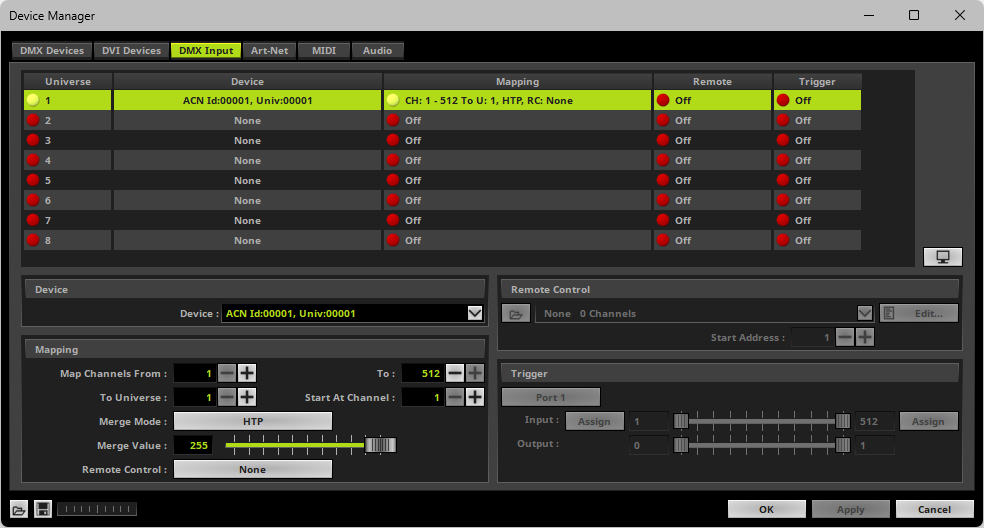
▪Configure the following settings in the section Mapping
- Map Channels From - Defines which incoming channels are used. This is the start channel to specify the range of channels.
- To - Defines which incoming channels are used. This is the end channel to specify the range of channels.
- To Universe - Defines onto which DMX output universe the specified range of incoming channels should be mapped.
[When mapping several DMX Input Universes/input devices to the same Universe, data will be processed one universe after another and the second DMX Input Universe is being mapped onto the result of the first DMX Input Universe, and so on.]
- Start At Channel - Defines the first DMX channel of the DMX output universe that should be used.
▪Merge Mode - You can map incoming data to a DMX address range that MADRIX 5 already controls. When merging data, the potential DMX output of MADRIX 5 is merged onto the incoming signal.
Merge Mode defines how that DMX output universe is merged onto the incoming data. Choose from the options below as the best choice depends on your usage scenario. The default setting is HTP.
[Merge Value, see below, defines how much data is merged. Merge Mode and Merge Value can be controlled via Remote Control]
- Input Only - Disables the merging of data. Solely the incoming signal will be mapped onto the DMX output universe. Merge Value is thus not available for this mode.
- HTP - Is short for Highest Takes Precedence. MADRIX 5 will compare incoming values with the potential DMX output. As a result, only the highest of both values on a particular channel will be sent to the output.
- LoTP - Is short for Lowest Takes Precedence. Is the opposite of HTP. MADRIX 5 will compare incoming values with the potential DMX output. As a result, only the lowest of both values on a particular channel will be sent to the output.
- Multiply - Incoming values will be multiplied with the potential DMX output, and then sent to output. [Values are converted to always ensure a maximum value of 255.]
- Multiply, Inverted - Incoming values will be multiplied with the potential DMX output, but the result will be inverted [low results will become high results and vice versa] before being sent to output. [Values are converted to always ensure a maximum value of 255.]
- Add - Incoming values will be added to the potential DMX output, and then sent to output.
- Subtract - Incoming values will be subtracted from the potential DMX output, and then sent to output.
- Subtract, Reversed - The potential DMX output will be subtracted from the incoming values, and then sent to output.
- XF - Is short for Cross-Fade. See also »Crossfader
- WF - Is short for White-Fade. See also »Crossfader
- MADRIX 5 Only - Does not factor in any incoming values and only the potential DMX output is sent to output. Merge Value is thus not available for this mode.
▪Merge Value - Defines how much of the potential DMX output is merged onto the incoming signal. A value of 0 means that no data from MADRIX 5 is merged onto the incoming signal, and thus only the incoming signal is mapped onto the universe. The default setting is 255. [Merge Mode and Merge Value can be controlled via Remote Control]
- XF and WF will have the same result as a fade from the crossfader. At 255, only the MADRIX 5 data is sent to output. See also »Crossfader
- All other Merge Modes behave like the Opacity value of a layer, whereas the upper layer is the MADRIX 5 data and the base layer is the incoming signal. See also »Layers
▪Remote Control - Allows you to assign a port to the DMX Input Universe for Remote Control
- Up to 8 ports can be assigned.
- You can then assign a DMX remote-control channel to this port in the »DMX-IN Remote Editor
- As such, you may assign a single port to a single DMX Input Universe/input device or you may assign the same port to several DMX Input Universes/input devices, thereby controlling several different input merges with a single DMX channel.
- Each port remembers the settings for Merge Mode and Merge Value.
- When assigning several DMX Input Universes/input devices to the same port, the settings for Merge Mode and Merge Value will be synchronized across all of them.
- The default setting is None, which disables the option for remote control.
▪Use Remote Control, if you want to control the MADRIX 5 Software remotely
▪First, select your device in the list.
▪Right Mouse Click or Left Mouse Double-Click on the column Remote to set from Off to On [indicated by green light 
 ].
].
▪Select one of the built-in protocols in the section Remote Control as explained below
or create your own remote configuration.
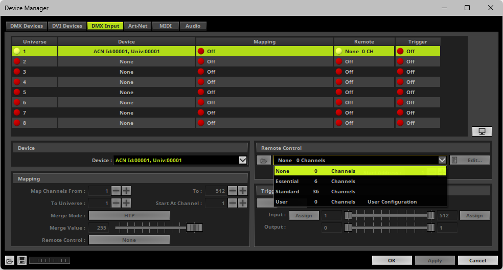
|
Open - Loads a previously saved MADRIX 5 DMX Remote Configuration file [of the file type *.mdrx]. |
|
Protocols - Choose from a pre-configured protocol [configuration]. |
|
DMX-IN Remote Editor - Allows you to modify a configuration or create a new configuration. |
|
Start Address - Defines on which particular DMX channel the protocol should start. The whole protocol will be mapped to this new address area. |
Trigger
▪Use Trigger, if you want to use incoming signals for the MADRIX 5 TRI Effects.
▪First, select your device in the list.
▪Right Mouse Click or Left Mouse Double-Click on the column Trigger to set from Off to On [indicated by green light 
 ].
].
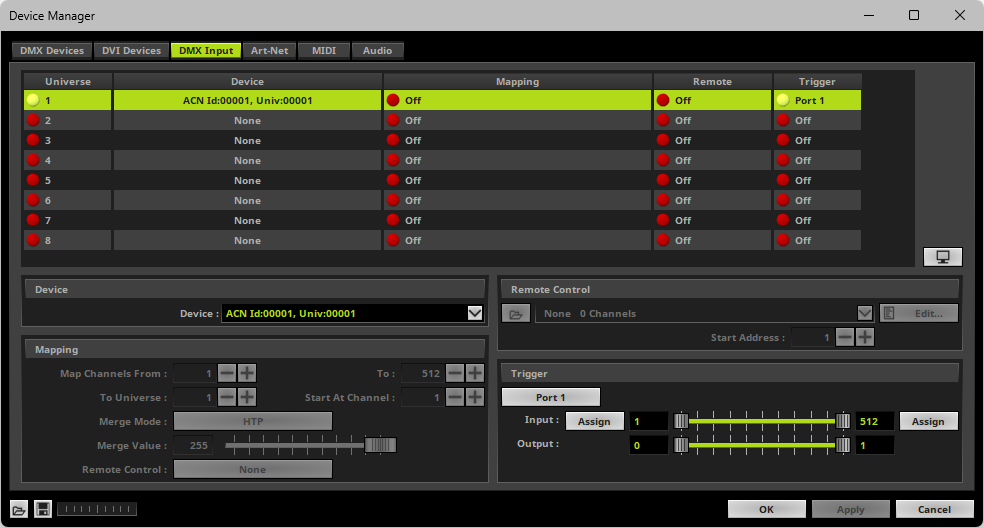
|
Port - Assigns a trigger port [Port 1 - 64] to this DMX-IN Device. MADRIX 5 allows you to send trigger signals from up to 64 different devices [64 ports] and assign a MADRIX 5 TRI Effect to the corresponding port. |
|
Input Value Range - Defines the DMX channels that are used for the trigger signal. [Incoming DMX values then usually determine the intensity of the effect.] |
|
Assign Minimum Value - Automatically assigns the minimum DMX channel when using the controller. |
|
Assign Maximum Value - Automatically assigns the maximum DMX channel when using the controller. |
|
Output Value Range - Defines how the input is mapped to the MADRIX 5 Effect. |
Learn more »[TRI] Trigger Effects
There are preprogrammed DMX protocols you can choose from:
▪Please make sure to save your MADRIX 5 Setup file after the configuration process.
| MADRIX 5.7. |
| [Ctrl & +/-] = Zoom In/Out | [Ctrl & 0] = 100% |
|
Previous Next
|
|
Enable Automatic Translation | Activer La Traduction Automatique | 启用自动翻译 |


