This topic includes:
MADRIX can control DVI-based LED products.
DVI output is particularly useful when using a video beamer [VGA or DVI, for example], a DVI video wall, the software LED Studio, on-screen capturing, or in similar fields of application.

The following MADRIX products support DVI output:
| ▪ | MADRIX KEY dvi start supports up to 512 native DVI pixels, for example 32x16 pixels. |
| ▪ | MADRIX KEY dvi entry supports up to 4,096 native DVI pixels, for example 64x64 pixels. |
| ▪ | MADRIX KEY dvi supports up to 307,200 native DVI pixels, for example 640x480 pixels. |
| ▪ | MADRIX KEY professional supports up to 786,432 native DVI pixels, for example 1024x768 pixels. |
| ▪ | MADRIX KEY ultimate supports up to 1,310,720 native DVI pixels, for example 1280x1024 pixels. |
| ▪ | Stretching and scaling to higher resolutions is possible with all these products. |
| ▪ | Please pay attention to other restricting factors, such as hardware limitations. Learn more »System Requirements |
| ▪ | If you do not connect a MADRIX KEY or a MADRIX interface to your computer, MADRIX will run in demo mode. |
| ▪ | In demo mode, every single feature will be available to you. MADRIX even sends output data [such as DMX512, Art-Net, etc.]; only the data output will be deactivated after each minute for a short period. |
| ▪ | Additionally, the following restrictions apply: - DVI output is overlaid by a colorful, rotating grid/cross. - You can see "NO MADRIX KEY". - The data output fully stops after 1 hour. You will need to restart the software to send restricted data again. |

Learn more »MADRIX KEY [Software License]
Configuration Of Microsoft Windows
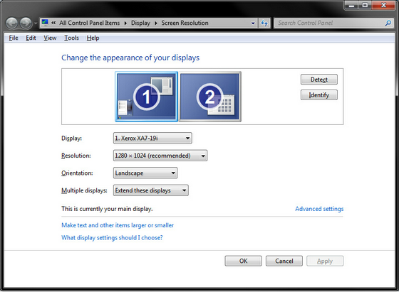
When using DVI output, make sure to configure the graphic card outputs in Windows first!
| ▪ | In Windows, go to Start > Control Panel > Display > Change display settings |
| ▪ | Windows shows all detected graphic card output ports - Click Detect to search for undetected outputs. |
| ▪ | Resolution - Defines the pixel resolution of this output port. [When working with DVI, it is often necessary to position the DVI output precisely and exactly where needed. The resolution is an important information that helps you set up your DVI output.] |
| ▪ | Multiple displays - Defines the display mode. The recommended setting is Extend these displays |
| ▪ | Confirm any changes with Apply |
| ▪ | Close the window with OK |
Make sure to configure your virtual LED matrix in MADRIX before using DVI output.
Configuration of the virtual LED matrix is a requirement!
You can use the Matrix Generator or the more advanced Patch Editor for this task.
Learn more »Matrix Generator or »Patch Editor
MADRIX features 2 DVI outputs.
| ▪ | External Preview 1 |
| ▪ | External Preview 2 |
Moreover, there are 3 modes available for DVI output:
| ▪ | DVI |
| ▪ | Window |
| ▪ | Full Screen |
| ▪ | DVI - Activates a floating, borderless DVI window. This is the most important DVI output. It is especially useful when using on-screen capturing. A well know example is the software LED Studio, which uses screen capturing. |
| ▪ | Window - Opens a floating window with a border. This might be a useful option if you choose to use DVI output as an additional preview window. |
| ▪ | Full Screen - Enables a floating, borderless full screen window to fit the entire output device. This is particularly useful for output devices, such as projectors, beamers, monitors, and large TV screens. |
| ▪ | Often, 1 DVI output will be enough for your LED project. But in certain cases you might need 2 DVI outputs [for example when your DVI video processor needs 2 inputs to drive a large number of pixels]. |
| ▪ | If you do not need the second DVI output, you may simply use it as another preview window or not use it at all. |
1] Activate DVI Output.
2] Configure DVI Options.
3] Configure External Window Settings.
1] Activating DVI Output
To activate DVI output:
| ▪ | Go to Previews > External Preview 1 > DVI |
| ▪ | Or choose Previews > External Preview 1 > Window |
| ▪ | Or choose Previews > External Preview 1 > Full Screen |
To activate the second DVI output:
| ▪ | Go to Previews > External Preview 2 > DVI |
| ▪ | Or choose Previews > External Preview 2 > Window |
| ▪ | Or choose Previews > External Preview 2 > Full Screen |
2] DVI Options
Each of the DVI outputs has a context menu.
This menu makes various options available to you for External Preview 1 and External Preview 2, respectively.
Note: Should an option be grayed out, it is not available at this moment or for this particular DVI output.
| ▪ | Go to Previews > External Preview 1 [or Right Mouse Click on the DVI window] |

| ▪ | DVI - Is explained above. |
| ▪ | Window - Is explained above. |
| ▪ | Full Screen - Is explained above. |
| ▪ | External Preview Settings... - Opens a new window with very useful and important settings for DVI output. Learn more External Preview Settings |
| ▪ | Lock Position - Locks the DVI output to the current position. It cannot be moved around with the mouse anymore. You can still change the position in the External Window Settings. |
| ▪ | Keep Always On Top - Brings the DVI output in front of all other windows at all times. No other window will overlap the DVI output. |
| ▪ | Move To Next Screen - Moves the output to the next monitor or graphics card output port. This option is only available for Full Screen. Learn more Switching Screens In Full Screen Mode |
| ▪ | 3D Mode - Activates the 3D mode for the output. This option is only available for Window and Full Screen |
| ▪ | 2D Mode - Activates the 2D mode for the output. This is the default mode. |
| ▪ | DVI Map Mode - Enables an individual DVI Patch, including DVI Mapping. This option is only required if you are using a DVI Patch. Learn more »DVI Patch |
| ▪ | Stretch Pixels - Scales the content to the maximum size of your preview window. This option is only available for Window and Full Screen |
| ▪ | Show Status Information - Displays extra information of the DVI output, such as the size of the matrix or the frame rate. This option is only available for Window and Full Screen |
| ▪ | Show Clock - Shows the time on the DVI output. This option is only available for Window and Full Screen |
| ▪ | Show Grid - Overlays the DVI window with a grid to show the individual pixels. This option is only available for Window and Full Screen |
| ▪ | Show Pivot Element - Displays a helpful icon for visual guidance. Three arrows are always shown at position X=0, Y=0, Z=0 [not matter if the Preview is rotated]. The X-axis is red [horizontal; width], the Y-axis is green [vertical; height], and the Z-axis is blue [level; depth]. This option is only available for Window and Full Screen |
| ▪ | Show Background Image... - Allows you to use a picture instead of the gray background. This option is only available for Window and Full Screen |
| ▪ | Default View - Choose your point of view and the default view for this output. This option is only available for 3D Mode |
| ▪ | Restore Default View - Resets the Preview to its Default View. This removes any changes, such as zoom or relocation. |
| ▪ | Close - Closes the DVI output. |
External Preview Settings are an important part of the DVI output configuration!
| ▪ | Go to Previews > External Preview 1 > External Preview Settings... [or Right Mouse Click on the DVI window > External Preview Settings... ] |

| ▪ | DVI Window Position - Defines the exact position of the DVI output for DVI - The coordinate system used for this starts with 0,0 at the top left of the entire screen/monitor. In this way, Left: defines the X coordinate and Top: represents the Y coordinate. - Valid values range from -10,000 to 10,000. |
| ▪ | DVI Window Size - Determines the actual size of the DVI output for DVI - Activate Use Display Area Size to set the size of the window to the settings of Display Area, which determines what is shown of your matrix. - Using different values for Width and Height than the maximum size of the Display Area will stretch or compress the content [you can make the window size smaller or bigger, but the pixel resolution will stay the same resulting in an image that is stretched or compressed. - The pixel resolution is set using the »Matrix Generator or »Patch Editor]. |
| ▪ | Display Area - Defines what is shown in the DVI ouput. This option is available for all 3 DVI output modes. - Activate Use Full Size and your complete LED matrix will be displayed. Or you can select a certain cut-out and specify which details of your matrix will be shown. You can choose the start coordinates and the end coordinates of this area. - Left and Top define the start coordinates in a coordinate system that starts with 0,0 in the top left corner. For example, for the default matrix with 50x50 pixels, Left and Top are 0 by default and Right and Bottom are 49, by default. - Right and Bottom define the end coordinates. The end coordinates cannot be higher than the full size of the matrix. For example, for the default matrix with 50x50 pixels, Left and Top are 0 by default and Right and Bottom are 49, by default. |
| ▪ | Slice Alignment - Is particularly relevant when using 3D and DVI-based LED fixtures that require a 2D input signal. This option is available for all 3 DVI output modes. Learn more Slice Alignment |
| ▪ | Display Transformation - Allows you to flip or rotate the DVI output. This option is available for all 3 DVI output modes. - None does not flip the output, Flip H flips it horizontally, Flip V flips it vertically, Flip HV flips it horizontally and vertically. - Rotate the output by 0° degrees [no rotation], 90° degrees, 180° degrees, or 270° degrees clock-wise. This rotation applies to the Display Area. |
| ▪ | Click Apply to confirm your changes. Click OK to close the window. |
| ▪ | Defaults - Restores the default settings. [These settings represent a standard 1:1 DVI window.] - If you have set up custom settings, MADRIX will show a check mark in front of External Window Settings... in the menu. |
3D Mapping For DVI
| ▪ | MADRIX can control 2D projects as well as 3D projects. Learn more »2D Or 3D [X, Y, Z] |
| ▪ | The chapters »Patch Editor and »DVI Patch already explained that DVI-based fixtures are often used in combination with a DVI controller. Such a DVI controller might require to receive the incoming single in a specific way to receive the correct image on the LEDs. This is true for 2D and controlling a 3D project adds further complexity. |
| ▪ | DVI controllers usually do not accept any 3D input image. That is why, you will often need to send a 2D signal to the DVI controller, even though your project might be in 3D. |
| ▪ | MADRIX can create Slices to produce such a 2D signal for 3D projects. |
| ▪ | By default, each Z-level is placed beside the previous Z-level from left to right. |
| ▪ | You can change the Slice Alignment for DVI, Window, as well as Full Screen. |
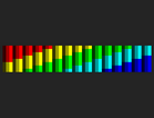
Example
| ▪ | The following example was chosen to explain Slice Alignment and 3D mapping for DVI. |
| ▪ | A virtual LED matrix of 15x8x3 is used. |
| ▪ | The first Z-level is the brightest, while the second and third Z-level have their Opacity increasingly reduced. |
| ▪ | A color gradient is applied as lighting effect. |
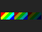
View |
3D Mode [Preview Left] |
Default View: Left |
|
Default View: Top |
|
Default View: Front |
|
Slice Alignment Settings
| ▪ | Go to Previews > External Preview 1 > External Preview Settings... > Slice Alignment |
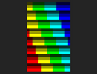
| ▪ | You can set up the Slice Type. Choose from X-Slices, Y-Slices, or Z-Slices |
| ▪ | You can set up the Slice Order. Choose from Left To Right, Right To Left, Top To Bottom, or Bottom To Top |
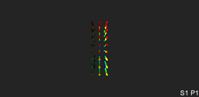
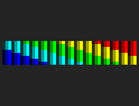
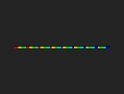
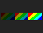
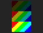
| ▪ | X-Slices - MADRIX produces slices along the X-axis. Since X = 15 regarding the virtual LED matrix in the example above, 15 slices are produced below. Above, Default View: Left can be used to imagine the different slices from the front to the back. |
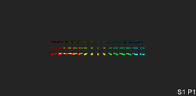
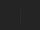
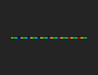
| ▪ | Y-Slices - MADRIX produces slices along the Y-axis. Since X = 8 regarding the virtual LED matrix in the example above, 8 slices are produced below. Above, Default View: Top can be used to imagine the different slices from the front to the back. |
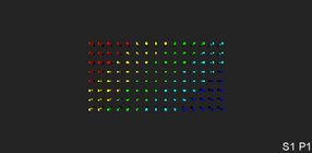
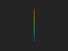
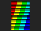
| ▪ | Z-Slices - MADRIX produces slices along the Z-axis. Since X = 3 regarding the virtual LED matrix in the example above, 3 slices are produced below. Above, Default View: Front can be used to imagine the different slices from the front to the back. |
| ▪ | Z-Slices / Left To Right is the default setting. |
|
Left To Right |
Right To Left |
Top To Bottom |
Bottom To Top |
X-Slices |
|
|
|
|
Y-Slices |
|
|
|
|
Z-Slices |
[Default] |
|
|
|

| ▪ | Each DVI Output is a Preview at the same time. That means you have various options to work with them as DVI output or Preview. Learn more »3 Previews |
| ▪ | This manual includes additional examples on how to set up DVI output. Learn more »DVI Examples |
Switching Screens In Full Screen Mode
You may want to send your Full Screen DVI output to another screen that is not the one you are using MADRIX on. This could be a second monitor or a projector, for example.
One Monitor
| ▪ | Use the keyboard shortcut Alt+Tab to switch to the Full Screen Output. |
| ▪ | Use the Alt+Tab again to switch back to the MADRIX user interface. |
Several Monitors
| ▪ | Make sure to select the full screen DVI output with your mouse [left mouse click]. |
| ▪ |
| ▪ | Or choose Right Mouse Click > Move To Next Screen |
| ▪ | In this way you can use the Full Screen mode to completely visualize effects on your second monitor or output device, while you are working with MADRIX on your first screen. |
You must install and configure your graphics card and monitors correctly in Windows first to use this feature!

You can upscale or downscale the DVI Output.
That means you can increase or decrease its size without changing the native pixel resolution [as defined in the Matrix Generator or Patch Editor].
| ▪ | Activate a DVI output as described above. - For example, go to Previews > External Preview 1 > DVI |
| ▪ | Go to Previews > External Preview 1 > External Preview Settings... |
| ▪ | Deactivate Use Display Area Size in the section DVI Window Size |
| ▪ | Set up Width as well as Height according to your requirements. - Use larger values to upscale the output. - Use smaller values to downscale the output. |
| ▪ | It is recommended to use multiples of the native pixel resolution [in order to not stretch the output]. - Example: Your virtual LED matrix might have a pixel resolution of 50x50 pixels. Enter 25x25 or 100x100 to use multiples of that resolution. |
| ▪ | Upscaling requires less performance than using a native pixel resolution but negatively affects the image quality in most cases. |
Further settings are available in the MADRIX Options.
Learn more »Performance
| ▪ | Please make sure to save your MADRIX Setup file after the configuration process. |