This topic includes:
This chapter is an addition to the chapter »Patch Editor
Please read the chapter Patch Editor in order to learn more about the Patch in general. This chapter focuses on working with DVI fixtures.
Patch Editor and DVI Patch are about one and the same tool. The term DVI Patch specifically refers to working with DVI fixtures.
| ▪ | Go to Preferences > Patch Editor [Keyboard shortcut: F3] |
On the one hand, working with DMX-based fixtures is relatively easy and can be managed with the help of the Patch Editor without much difficulty. You can simply add fixtures, rotate them, or add space between fixtures, for example. Without the DVI Patch, on the other hand, it would not be possible to add rotation or spacing to DVI-based fixtures, because of how DVI hardware controllers work.
The DVI Patch allows you to add
| ▪ | rotation |
| ▪ | flipping |
| ▪ | spacing |
to your LED installations with DVI fixtures.
The DVI Patch can be used when working with DVI fixtures and the following output methods:
| ▪ | »DVI |
How DVI Hardware Controllers Work
DVI controllers receive a signal [input] and map it to the LED fixtures [output]. But due to their construction, DVI controllers usually need to receive the input images in a linear way, in one whole block of information [often like a rectangle] — no matter how the actual LED installation looks like.
You could also say that DVI controllers expect DVI fixtures to be installed in a predefined way. If you install the DVI fixtures differently, you need to change the input, too.
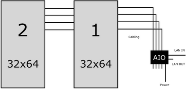
In other words, when your LED installation looks like this for example:
![]()
Then, your DVI controller will probably need the input signal to look like this:

This is no problem for MADRIX. It will transform the signal for your DVI controller according to your Patch configuration.
While the DVI fixtures represent your LED installation in MADRIX and its Previews, you can customize their DVI Mapping settings for the controller that receives the signal. As shown above, DVI fixture settings and their DVI Mapping often are two different things if you add rotation, flipping, or spacing. That is why you will have to configure the normal DVI fixture settings and their DVI Mapping settings separately.
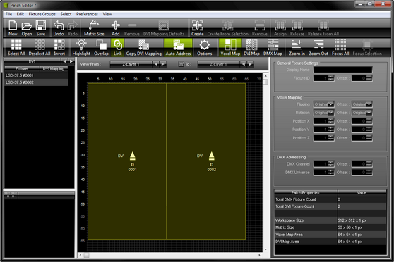
The Patch Editor provides three view modes. Regarding the DVI Patch the DVI Map is of special importance, since makes it possible to configure the required DVI Mapping of the DVI fixtures.
In order to work with DVI fixtures, follow the instructions below:
1] Position your DVI fixtures in the graphical workspace of the Patch Editor according to your LED installation [using the view mode Voxel Map].
2] Set up the size of your virtual LED matrix [the Matrix Size]. Normally, the area it defines should include all of your DVI fixtures.
3] Activate the view mode DVI Map [Keyboard shortcut: F6] in the Patch Editor.
4] Adjust the DVI Mapping of every single DVI fixture according to the requirements of your DVI hardware controller. [The DVI Mapping of the first DVI fixture normally starts at position X:1, Y:1.]
5] When using »DVI, activate the DVI Map Mode of the external DVI Outputs. When using »Proprietary DVI Devices [5A / A8 / T9], Step 5 is not required.
Step 1 and 2 are explained in the chapter »Patch Editor
Step 3, 4, and 5 will be explained below.
Step 3, 4, and 5 are only necessary, if you wish to add spacing, rotation, or flipping to your Patch that includes DVI fixtures.
Overview

The DVI Mapping of DVI fixtures represents the fixture configuration for the DVI hardware controller. DVI Mapping settings can include their own position, rotation, and flipping settings. In order to work with DVI Mapping, you need to activate the DVI Map of the Patch Editor.
| ▪ | In the Patch Editor, select View > DVI Map [Keyboard shortcut: F6] |
You only need DVI Mapping if you are using DVI fixtures in a different way than what the DVI controller expects.
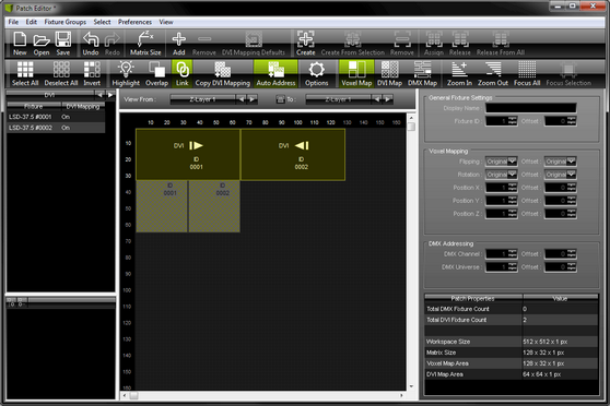
Comparison Of Voxel Map And DVI Map
DVI Mapping Shown In The Voxel Map |
DVI Mapping Shown In the DVI Map |
DVI Mapping is inactive in the Voxel Map. It is shown in gray with a diagonal grid. |
DVI Mapping is active in the DVI Map. It is shown in yellow with a diagonal grid. |
When DVI fixture and its DVI Mapping have the same position, the DVI fixture is shown. |
When DVI fixture its DVI Mapping have the same position, the DVI Mapping is shown. |
|
|
|
|
A] Disabled: If a DVI fixture is copied, the DVI Mapping is reset to its default settings. That means it will have the settings of the newly copied DVI fixture. In fact, the copied DVI fixture has its own DVI Mapping. B] Enabled: If a DVI fixture is copied, the DVI Mapping includes the same settings as the DVI Mapping of the source or the settings plus a corresponding offset. If activated, the icon glows green in the toolbar. |
In the DVI Map, DVI Mapping settings cannot be copied like DVI fixtures. Please switch back to the Voxel Map. |
|
|


 DVI fixtures can overlap. That means that one fixture can be positioned over another fixture. You need to activate the feature in the menu
  DVI fixtures can be copied very easily. Before copying a DVI fixture, you can decide how its DVI Mapping is handled during the copy process. Enable or disable the feature in the menu
 Restore the default DVI Mapping settings of selected DVI fixtures by choosing
Interaction And Settings

| ▪ | The DVI Mapping of DVI fixtures can be used and interacted with in the Patch Editor just as any other fixture. In other words, it can be positioned with the mouse or keyboard, for example. Learn more »Patch Editor |
| ▪ | You may also edit the DVI Mapping settings directly. - Make sure view mode DVI Map is active. - Select the DVI Mapping of a DVI fixture and go to the section DVI Mapping to the right. - You may change the Flipping, Rotation, or Position X, Position Y, Position Z. - You can also add or substract an Offset for each of these items. - Always confirm with OK Learn more »Patch Editor |
| ▪ | At the same time, the section Fixture Properties / Value shows all necessary information for the DVI Mapping. |
| ▪ | When working in 2D, make sure to position your DVI fixtures and their DVI Mapping always on the first Z-level. That means Position Z must be 1! |
| ▪ | Learn more »Patch Editor |
Activating DVI Map Mode For The External DVI Outputs
Please activate DVI Map Mode for your external DVI output.
Activating DVI Map Mode for the external DVI output is only necessary for screen-capturing.

| ▪ | The external DVI outputs offer a number of additional configuration settings. Make sure to configure everything as needed! Learn more »DVI |
How To Configure Two Rotated EUROLITE LSD 37.5
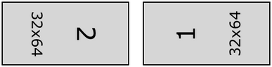
The normal setup of two EUROLITE LSD 37.5 fixtures looks like this [schematic]:
Sample Setup
In this example, we will configure the two fixtures to be installed like this [schematic; without space]:
Step 1] Adding DVI Fixtures
1] Create a new Patch. Select File > New Patch [Keyboard shortcut: Ctrl+N].
2] Add the two fixtures. Select Edit > Add Fixtures... [Keyboard shortcut: Ins]. Make sure to not select Merge Fixtures
Use the settings as shown in the screenshot:

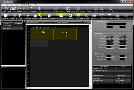
3] The Patch will look like this:
4] We need to rotate both fixtures to match the LED installation. The left fixture is rotated by 90°. The right fixture is rotated by 270°.
[If you receive an error message about the fixtures being out of range, move your fixture towards a free location on your workspace. Then, rotate them and move them back.]
Step 2] DVI Map
5] Switch to the DVI Map. Select View > DVI Map
[Keyboard shortcut: F6]
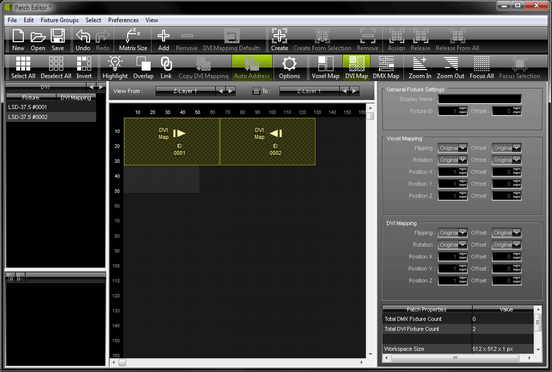
Step 3] DVI Mapping
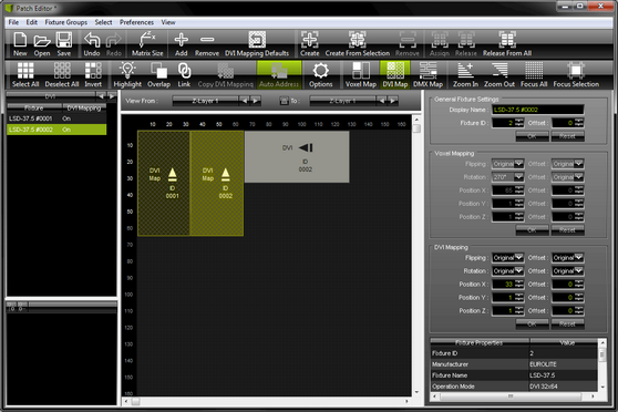
6] Deactivate Link
7] Select the first DVI fixture with its DVI Mapping and position it in the center of your workspace. In the section DVI Mapping, change Rotation to Original and click OK
8] Select the second DVI fixture with its DVI Mapping and position it in the center of your workspace. In the section DVI Mapping, change Rotation to Original and click OK
9] Arrange both DVI fixtures with their DVI Mapping next to each other in the upper left corner. The DVI Mapping of DVI fixture 1 is positioned at Position X: 1, Position Y: 1, Position Z: 1. The DVI Mapping of DVI fixture 2 is located at Position X: 33, Position Y: 1, Position Z: 1.
10] Switch back to the Voxel Map. Select View > Voxel Map [Keyboard shortcut: F5].
Step 4] Matrix Size
11] Select Edit > Matrix Size.... Enter Size X: 128, Size Y: 32, Size Z: 1, and Color Depth: 3. The virtual LED matrix now matches the size of both fixtures in total.
Step 5] Result
12] Your final Patch should look like this:
12] The DVI fixtures and therefore the 3 Previews will represent your LED installation:

| ▪ | It was necessary to configure the DVI Mapping of the fixtures separately because the DVI hardware controller expects to receive the input signal like this [also shown above in the Normal Setup]. |
| ▪ | The EUROLITE LSD 37.5 works with the EuroLite T9 protocol. No screen-capturing is needed and therefore DVI Map Mode does not need to be activated for the external DVI output window for this example. - [In most cases, you should activate DVI Map Mode for the external DVI output window for other fixtures and controllers.] |
Tips
| ▪ | Make sure that DVI Mapping and DVI fixtures are not linked in the DVI Map [Disable Link mode]. |
| ▪ | If you receive an error message about the fixtures being out of range, then move your fixture towards a free location on your workspace. |
Further Tips
Please make sure to save your MADRIX Setup file after the configuration process.
You may also save and/or export the Patch as a separate file [of the file type *.mpz or *.mpx].