This topic includes:
▪MADRIX USB contact closure, MADRIX USB temperature, MADRIX USB light sensor
MADRIX I/O is a product category for supplementary input and output devices.
External equipment, such as sensors, brings additional automation processes and interaction to any LED project using the MADRIX 5 Software.
The following accessories are included in this category:
MADRIX USB contact closure, MADRIX USB temperature, MADRIX USB light sensor

▪Registers if its internal circuit is either open or closed.
▪Can be used as connector for a digital switch or button, for example.
▪Is an input device.
▪Can simply be connected to any USB 2.0 port.
▪The recommended frame time ms / FPS is 500 / 2.
▪Incoming data directly translates into DMX data in MADRIX 5 .
▪Data is sent to DMX channel 1 - DMX channel 2 on your selected DMX universe.
▪Incoming DMX values on DMX channel 1 are 0 or 255 [Off or On].
▪Inverted incoming DMX values on DMX channel 2 are 255 or 0 [On or Off].

▪Can be used to measure the ambient light level.
▪Is an input device.
▪Can simply be connected to any USB 2.0 port.
▪The recommended frame time ms / FPS is 500 / 2.
▪Incoming data directly translates into DMX data in the MADRIX 5 Software.
▪Data is sent to DMX channel 1 - DMX channel 8 on your selected DMX universe.
▪DMX channel 1 represents the light level in percent. Valid values range from 0% to 100%.
▪DMX channel 2 represents the decimal place in percent. Valid values range from .0% to .99%.
▪DMX channel 3 represents the light level in DMX values. Valid values range from 0 to 255.
▪DMX channel 4 represents the decimal place in DMX values. Valid values range from 0 to 255.
▪DMX channel 5 represents the inverted light level in percent. Valid values range from 0% to 100%.
▪DMX channel 6 represents the inverted decimal place in percent. Valid values range from .0% to .99%.
▪DMX channel 7 represents the inverted light level in DMX values. Valid values range from 0 to 255.
▪DMX channel 8 represents the inverted decimal place in DMX values. Valid values range from 0 to 255.

▪Can be used as temperature sensor.
▪Is an input device.
▪Can simply be connected to any USB 2.0 port.
▪The recommended frame time ms / FPS is 1000 / 1.
▪Incoming data directly translates into DMX data in MADRIX 5 .
▪Data is sent to DMX channel 1 - DMX channel 10 on your selected DMX universe.
▪DMX channel 1 represents the temperature in degree Celsius. Valid values range from -20 °C to +80 °C.
▪DMX channel 2 represents the decimal place of degree Celsius. Valid values range from .0 to .99.
▪DMX channel 3 shows if the temperature values shown on DMX channel 1 are above zero [0] or below zero [255].
▪DMX channel 4 is not used.
▪DMX channel 5 represents the temperature in degree Fahrenheit. Valid values range from -4 °F to +176 °F.
▪DMX channel 6 represents the temperature decimal place of degree Fahrenheit. Valid values range from .0 to .99.
▪DMX channel 7 shows if the temperature values shown on DMX channel 5 are above zero [0] or below zero [255].
▪DMX channel 8 is not used.
▪DMX channel 9 represents the temperature in DMX values. Valid values range from 0 to 255.
▪DMX channel 10 represents the decimal place of DMX values. Valid values range from 0 to 255.
1] Connect your device.
2] Enable drivers in the MADRIX 5 Software.
3] Enable your device.
4] Set up DMX Input.
5] Choose how to use incoming data.
1] Connect Your Device
▪Connect your MADRIX I/O device to a free USB 2.0 port of your computer.
▪Make sure that Windows recognizes the device. Windows will automatically install the drivers for the device.
2] Enable Drivers In The MADRIX 5 Software
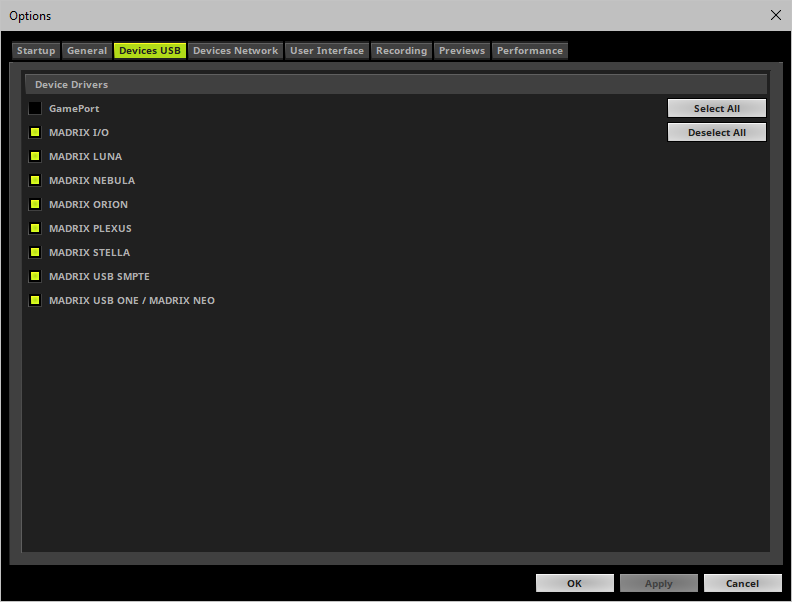
▪Go to the menu Preferences > Options... > Devices USB
▪Activate MADRIX I/O
[The option is activated by default.]
▪Click Apply and OK
3] Enable Your Device
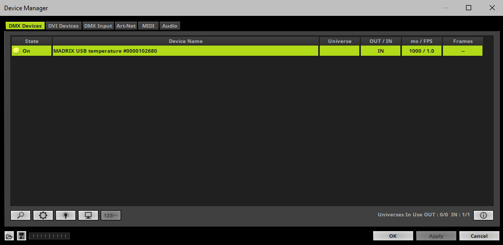
▪Go to the menu Preferences > Device Manager... > DMX Devices
▪Click ![]() if your device is not shown in the list.
if your device is not shown in the list.
▪Select your device in the list. Right Mouse Click on the column State to set it from Off to On
▪It is not recommended to change the frame time ms / FPS of your device. Instead, it is highly recommended to use the default settings. [Recommended settings are provided above.]
4] Set Up DMX Input
▪Go to the menu Preferences > Device Manager... > DMX Input
▪Select one entry in the list [e.g., Universe 1] and go to the section Device. Choose your device under DMX-IN Device
▪The MADRIX 5 Software now receives data from your device.
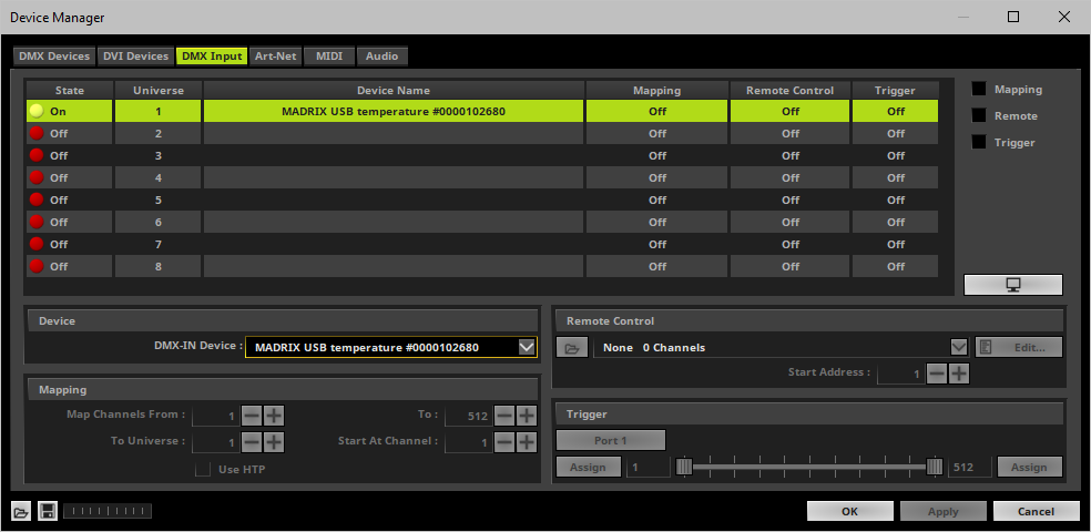
5] Choose How To Use Incoming Data
Now, you have several options to choose from:
A] You can activate Remote and choose a protocol in the section Remote Control. This will allow you to control the MADRIX 5 Software remotely using your controller. Learn more »DMX-IN / Art-Net Remote / sACN Input
B] You can use incoming data in a Script or Macro. Learn more »Macros And Scripts
C] You can activate Trigger and choose the trigger functionality in the section Trigger.
D] You can monitor incoming DMX data in the DMX Watcher. Select your device in the list and click  Learn more below.
Close the Device Manager with OK
To effectively work with incoming DMX data from your device, you can use the DMX Watcher to monitor incoming signals.
▪Open the DMX Watcher as explained above or go to the menu Tools > DMX Watcher...
▪Select Input
▪Set up the correct Universe
- This is the same number as you have chosen in the list under Preferences > Device Manager... > DMX Input [e.g., Universe 1].
Overview

▪This input device allows you to effortlessly use SMPTE time code for time synchronization across devices.
▪Data is received via the 3-pin, female XLR connector.
▪The device can simply be connected to any USB 2.0 port.
Step-By-Step Configuration
1] Connect your device.
2] Enable drivers in the MADRIX 5 Software.
3] Use a Cue List.
1] Connect Your Device
▪Connect your SMPTE time code source to the 3-pin, female XLR connector of MADRIX USB SMPTE.
▪Make sure that your SMPTE time code source is sending data.
▪Connect your MADRIX USB SMPTE to a free USB 2.0 port of your computer.
▪Make sure that Windows recognizes the device. Windows will automatically install the drivers for the device.
2] Enable Drivers In The MADRIX 5 Software
▪Go to the menu to Preferences >Options... > Devices USB
▪Activate MADRIX USB SMPTE
[The option is activated by default.]
▪Click Apply and OK
3] Use A Cue List
Cue Lists are the feature in the MADRIX 5 Software to receive Time Code.
▪Go to the menu Tools > Cue Lists...
▪Or press F7
▪Or click Layers > Cue Lists on the user interface.
▪Select the Time Code source SMPTE
▪Select the required Time Code Format
▪The MADRIX 5 Software will automatically start receiving external Time Code.
▪The Time Code format is HH:MM:SS:FF [hours:minutes:seconds:frames]
Example:
- 10 o'clock and 20 minutes, 30 seconds, and 10 frames will be shown as
10:20:30:10

▪Configure the column Time Code for your Cue List entries.
▪Add or edit more entries according to your requirements.
▪Learn more »Cue List Editor
To ensure interruption-free operation of the software and devices, please make sure to check the power-saving settings of Windows.
Learn more »PC Power Management
| MADRIX 5.7. |
| [Ctrl & +/-] = Zoom In/Out | [Ctrl & 0] = 100% |
|
Previous Next
|
|
Enable Automatic Translation | Activer La Traduction Automatique | 启用自动翻译 |