This topic includes:
▪When To Use The Matrix Generator
▪Examples For Start Corner, Main Orientation, and Snake Mode
You need to tell the MADRIX 5 Software
1] which LED fixtures you are going to use.
2] how many LED fixtures you are going to use.
3] how they are placed.
This configuration of the virtual LED matrix is stored in a so-called Patch file.
Setting up the virtual LED matrix/the Patch file is a requirement! It is necessary for the initial configuration of MADRIX 5.
MADRIX 5 offers 2 tools for this task:
▪Matrix Generator
▪Patch Editor
When To Use The Matrix Generator
The Matrix Generator helps you to generate a virtual LED matrix automatically according to your settings. This automatic process can be very helpful, when your LED installation is set up in a very simple, logical, or linear way and only uses 1 fixture type. The Patch file will be automatically generated by MADRIX 5 for you.
The Patch Editor is a graphical editor to directly create the Patch file. The Patch Editor offers the same functions as the Matrix Generator and many more options. It allows you to configure your virtual matrix in great detail. You can place LED fixtures freely and individually. If you have more than 1 kind of fixture, use the Patch Editor.
This topic explains the Matrix Generator.
▪Go to Preferences > Matrix Generator...
[Keyboard shortcut: F2]
▪A new window will open.
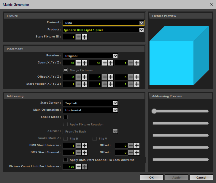
▪Now, configure your virtual LED matrix according to the following settings.
To work with the Matrix Generator, follow these steps:
1] Open the Matrix Generator.
2] Set up all settings, including Fixture, Placement, and Addressing.
3] Click Apply to confirm your settings and MADRIX 5 will create the Patch file automatically for you.
- Click OK to confirm your settings and to close the Matrix Generator.
- Click Cancel to discard any changes and to close the Matrix Generator.
In this user guide it is not possible to give universal recommendations for the required settings, because every LED project is different. You need to configure the settings of the Matrix Generator according to your individual LED setup.
1] Fixture
This section defines which fixtures you want to use.
To assist you, a Fixture Preview is shown that includes the start channel in blue, the number of pixels, and orientation. [Imagine to look directly at the LED products in camera view.]
▪Protocol - First, choose the general type of LED fixture you are using [DMX or DVI].
- DMX-based fixtures include DMX512, Art-Net, Streaming ACN [sACN / E1.31], Color Kinetics [KiNET], and Philips hue.
- DVI-based fixtures include DVI, ColourSmart Link, Colorlight A8, Colorlight 5A, Colorlight T9, and Eurolite T9 products.
- If you wish to used both fixture types at the same time, please configure your virtual LED matrix with the help of the »Patch Editor
Note: If DVI is selected, all controls that are not relevant to DVI fixtures will be disabled.
▪Product - Second, choose your exact LED product.
- You can use the downward triangle to call up the complete list of fixtures.
- Perform a left mouse click and you can use the input field as a filter to type in the fixture you are looking for.
- If your fixture is not yet available, please see »Supported Fixtures [LED Products]
▪Start Fixture ID - Defines where MADRIX 5 starts indexing fixtures. The Fixture ID is a unique identifier for each fixture that is added.
- The default value is 1.
- When using the Matrix Generator, the default setting is also recommended setting.
- When using the Patch Editor, the Start Fixture ID needs to be a number that is not yet occupied by fixtures in the Patch. Each fixture needs its own, unique Fixture ID. MADRIX 5 will automatically provide the next number that is free to use. [You will not be able to add new fixtures if an ID is not unique.]
▪A general option for DMX: Select !generic RGB Light 1 pixel for any LED product with RGB LEDs and 3 DMX channels.
▪A general option for DMX: Select !generic RGBW Light 1 pixel for any LED product with RGBW LEDs and 4 DMX channels.
▪A general option for DVI: Select !generic DVI 1x1 RGB for any DVI-based LED product and simply enter the pixel resolution under Placement
2] Placement
This section defines how many fixtures you want to use and how they are placed.
▪Rotation - Uses the original rotation of the fixtures, as defined in the »MADRIX 5 Fixture Editor. Or you can add to all of your fixtures a rotation of 90°, 180°, 270°.
▪Count X / Y / Z - Defines the number of LED fixtures you are using.
- X sets the number of fixtures on the X-axis [horizontal; width].
- Y sets the number of fixtures on the Y-axis [vertical; height].
- Z sets the number of fixtures on the Z-axis [level; depth].
- Please set up the number of fixtures you are using. Do not enter the total number of pixels. All fixtures profiles are already implemented with their specific number of LED pixels.
- When setting up a 2D virtual LED matrix, Z should be 1. If Count Z is higher than 1, you will automatically create a 3D LED matrix.
- The maximum value that can be entered is 65536. The number that can actually be used by you has theoretic limits as well as practical limits. Learn more Limitations
▪Merge Fixtures - Is only available for Protocol > DVI.
- Activate this option if all your DVI fixtures, should be merged to one fixture. This can save computer performance.
- Deactivate this option, if you want to be able to manage all your DVI fixtures separately, for example when creating a »DVI Patch
▪Offset X / Y / Z - Adds spacing [gaps] to your virtual LED matrix separately for the X-axis, Y-axis, and Z-axis.
- The value defines the size of the gaps between fixtures in pixels.
- A value of 0 means that all fixtures are placed next to each other without spacing.
- For example, a value of 1 means that 1 pixel spacing is added between fixtures.
▪ Start Position X / Y / Z - Positions fixtures correctly on the workspace.
- In case of the Patch Editor, it can prevent fixtures to overlap. In general, you will not be able to add new fixtures if their positions overlap. However, you can intentionally allow overlapping fixtures if you want to. »Learn more
▪Note: When using DMX-based products, please pay attention to the maximum number of DMX channels according to your MADRIX 5 License and according to the performance of your PC.
▪Note: When using DVI-based products, please pay attention to the maximum number of supported DVI voxels according to your MADRIX 5 License and according to the performance of your PC.
3] Addressing
This section defines the numbering of fixtures [DVI] and addressing of fixtures [DMX]. Since MADRIX 5 will do this automatically, certain parameters need to be specified by you on how MADRIX 5 should number or address fixtures automatically.
To assist you, a graphic is shown. [Imagine to look directly at the LED products in camera view.]
Please note: All fixture profiles are automatically working in HTP mode [Highest Takes Precedence].
[For example, you have 2 fixtures with the same DMX address. But due to their different locations in the MADRIX Patch, they receive different color values. Because HTP is activated for these fixtures, the highest color value will be put out onto the LEDs.]
When using the Patch Editor, you can choose not to set up all Addressing in the Add Fixtures window. The Patch Editor allows you to configure each fixture individually later.
▪Start Corner - Defines where the automatic addressing starts and works together with Main Orientation. Learn more Examples
▪Main Orientation - Defines if MADRIX 5 automatically addresses fixtures in a horizontal or vertical way. Addressing will start at the Start Corner and continue to the opposite direction [e.g., from left to right]. Please see the example below. Learn more Examples
▪Snake Mode - Without Snake Mode, MADRIX 5 will address row by row or column by column [e.g., left to right, left to right, left to right, etc.]. With Snake Mode, MADRIX 5 will use alternate directions for each row or column [e.g., left to right, right to left, left to right, etc.]. Learn more Snake Mode
▪Apply Fixture Rotation - Only works when Snake Mode is enabled. Rotates fixtures in each alternating row by 180°.
▪Z-Order - Is only available for 3D. Defines if addressing in 3D starts with the first Z-axis in front [Front To Back] or with the last Z-axis in the back [Back To Front].
▪Snake Mode Z - Is only available for 3D. Automatic addressing of fixtures on the Z-axis is done level by level. Activate this option if the Start Corner for each alternating level should be different.
- Flip H - Switches the Start Corner horizontally [e.g., from Top Left to Top Right].
- Flip V - Switches the Start Corner vertically [e.g., from Top Left to Bottom Left].
- Activate both, Flip H and Flip V, to assign the complete opposite Start Corner [e.g., from Top Left to Bottom Right].
▪DMX Start Universe - MADRIX 5 will start addressing using this DMX universe and automatically increment the DMX universe for each fixture when necessary.
- A total of 512 DMX channels is available per DMX universe.
- If your fixture addressing is greater than 512, MADRIX 5 will automatically assign a new DMX universe and start at DMX channel 1 in this new universe again.
- The maximum number that can be entered has theoretic limits as well as practical limits. Learn more Limitations
- When using the Patch Editor, MADRIX 5 will automatically calculate the next free start universe according to the fixture profile you have currently selected [Fixture > Product] and according to any changes you are making regarding your Patch.
- In order for this to work, Auto-Address needs to be enabled in the Patch Editor [Preferences > Automatically Address New DMX Fixtures].
- Offset - Allows you to define deviating addressing when fixtures need to be assigned to a new universe.
- For example, fixtures are assigned to universe 1, 5, and 9 with an offset of 3, instead of the linear way of 1, 2, and 3.
▪DMX Start Channel - MADRIX 5 will start the addressing using this DMX channel and automatically increment the DMX channel for each fixture.
- Valid values range from 1 to 512.
- Note: The maximum viable start channel will be calculated by the software depending on the fixture. E.g., for a 3-channel fixture, the maximum DMX Start Channel can be set as 510. If you need to set it to a higher value, you can do so manually in the »Patch Editor
- When using the Patch Editor, MADRIX 5 will automatically calculate the next free start channel according to the fixture profile you have currently selected [Fixture > Product] and according to any changes you are making regarding your Patch.
- In order for this to work, Auto-Address needs to be enabled in the Patch Editor [Preferences > Automatically Address New DMX Fixtures].
- Offset - Allows you to quickly add additional values to the addresses of each newly created fixture.
- For example, 3-channel fixtures will have start channels 1, 11, 21, 31, etc. with an offset of 7, instead of 1, 4, 7, 10, etc.
▪Apply DMX Start Channel To Each Universe - Uses the entered value for each DMX universe instead of only the first universe.
▪Fixture Count Limit Per Universe - Defines the maximum number of fixtures the MADRIX 5 Software will place and address in a single DMX universe.
- By default, the maximum number will automatically be provided. Adjust the number as needed or leave the default value.
4] Confirmation
▪Click Apply to confirm your settings.
▪Click OK to close the window.
Examples For Start Corner, Main Orientation, and Snake Mode
Start Corner And Main Orientation
DMX Start Corner |
Main Orientation: Horizontal |
Main Orientation: Vertical |
Top Left |
Addressing: - Downwards |
Addressing: - To the Right |
Top Right |
Addressing: - Downwards |
Addressing: - To the Left |
Bottom Left |
Addressing: - Upwards |
Addressing: - To the Right |
Bottom Right |
Addressing: - Upwards |
Addressing: - To the Left |
▪Without Snake Mode, MADRIX 5 will address row by row or column by column [e.g., left to right, left to right, left to right, etc.].
▪With Snake Mode, MADRIX 5 will use alternate directions for each row or column [e.g., left to right, right to left, left to right, etc.].
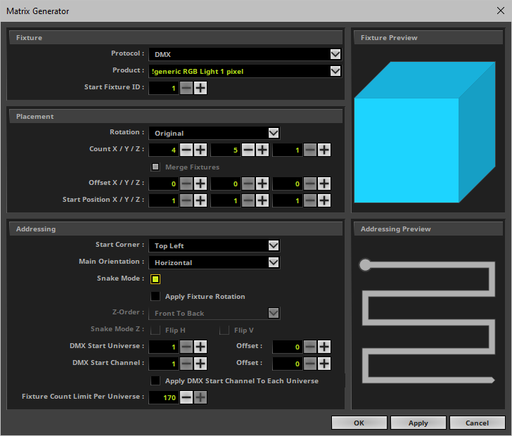
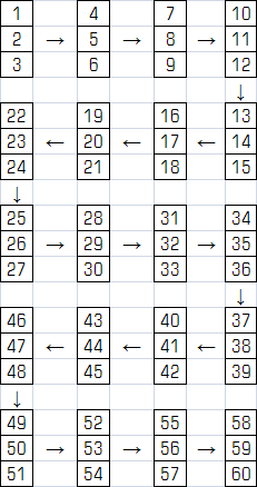
▪In this example we configured a virtual LED matrix of 4 x 5 pixels using Snake Mode
▪The Matrix Generator settings would look like this:
▪In theory, the LEDs are arranged as follows: 3 channels per LED [due to RGB], 4 fixtures per row, and a total of 5 rows. Please see the illustration below:
To configure a 2D LED matrix with DMX-based fixtures, follow these steps:
1] Choose Protocol > DMX
2] Choose your Product
3] Set up Rotation if required
4] Set up Count X and Count Y
5] Set Count Z to 1
6] Set up Offset X and Offset Y if required
7] Set Offset Z to 0
8] Set up Start Corner and Main Orientation
9] Set up Snake Mode and Apply Fixture Rotation if required
10] Set up DMX Start Universe, DMX Start Channel, and Fixture Count Limit Per Universe
To configure a 2D LED matrix with DVI-based fixtures, follow these steps:
Merge Fixtures
1] Choose Protocol > DVI
2] Choose your Product
3] Set up Rotation if required
4] Set up Count X and Count Y
5] Set Count Z to 1
6] Leave Merge Fixtures activated
Separate Fixtures
1] Choose Protocol > DVI
2] Choose your Product
3] Set up Rotation if required
4] Set up Count X and Count Y
5] Set Count Z to 1
6] Deactivate Merge Fixtures
7] Set up Start Corner and Main Orientation if required
8] Set up Snake Mode and Apply Fixture Rotation if required
To configure a 3D LED matrix with DMX-based fixtures, follow these steps:
1] Configure all Settings as described under Settings
To configure a 3D LED matrix with DVI-based fixtures, follow these steps:
Merge Fixtures
1] Choose Protocol > DVI
2] Choose your Product
3] Set up Rotation if required
4] Set up Count X and Count Y and Count Z
5] Leave Merge Fixtures activated
6] Set up Z-Order
Separate Fixtures
1] Choose Protocol > DVI
2] Choose your Product
3] Set up Rotation if required
4] Set up Count X and Count Y and Count Z
6] Deactivate Merge Fixtures
7] Set up Offset X / Y / Z if required
8] Set up Start Corner and Main Orientation if required
9] Set up Snake Mode and Apply Fixture Rotation if required
10] Set up Z-Order and Snake Mode Z if required
LED Fixtures |
Comments |
EUROLITE LSD |
The fixtures are pre-patched and included with their amount of pixels. Please only define how many fixtures you are using and not the total number of pixels. |
Color Kinetics eW Flex SLX, Color Kinetics iColor Flex SLX |
If your are using a PDS-150, a sPDS-480ca, or a PDS-60ca with one or two strings per controller, please select the correct fixture. |
Count X / Y / Z
▪The maximum value you can enter is 65536 by default.
▪Please note that this is a theoretical limit.
▪The maximum value that can be used depends on the capabilities of your computer.
- The graphics card needs to support these values. [The Logfile shows the highest available values for your current system via viewport size X and viewport size Y in combination with 2D texture size for 2D mode and 3D texture size for 3D mode. Search for these items or choose Filter > Previews. Learn more »Tools]
- The overall computer performance defines the maximum resolution your PC can handle in 2D or 3D. Learn more »System Requirements
- The available, contiguous memory also defines the maximum available resolution [RAM; up to the theoretic maximum of 2 GB as a 32-bit application, which is much lower in practice].
▪Examples:
- It is not feasible to set up extremely high resolutions, such as 65536 x 65536 x 65536 or 500 x 500 x 500, for example.
- High values can be useful when setting up extremely rectangular 2D matrices, such as 10000 x 20 x 1 or 20 x 10000 x 1, for example.
DMX Start Universe
▪The maximum value you can enter is 2048 by default and the maximum value.
▪You can change the maximum value in by changing the Virtual DMX Universes setting in the Options.
Learn more »Performance
▪It is possible to use more virtual DMX universes than actual DMX universes by using less than 512 DMX channels per universe.
▪The actual number of DMX universes [i.e. DMX channels] that can be used for output depends on your MADRIX 5 License.
»MADRIX KEY [Software License]
▪MADRIX 5 offers many more options to configure your virtual LED matrix.
Learn more »Patch Editor
▪If your fixture is not yet available or if you would like to add it,
please see »Supported Fixtures [LED Products]
Make sure to save your MADRIX 5 Setup File after the configuration process.
| MADRIX 5.7. |
| [Ctrl & +/-] = Zoom In/Out | [Ctrl & 0] = 100% |
|
Previous Next
|
|
Enable Automatic Translation | Activer La Traduction Automatique | 启用自动翻译 |

