This tutorial shows you how to create a 2D patch for several DVI fixtures with the help of the Patch Editor.
Date: 10/2018
MADRIX Version: 5.0 (Created with)
Corresponding Video Tutorial: »Creating A 2D Patch For DVI Output With The Patch Editor
Note:
We will use the result of this task in the tutorial »Merge Patches, »Rotate Fixtures and »Layer Tiling With Offset. If you want to have a look also at this tutorials, it is recommended to save the patch at the end of the tutorial.
Task:
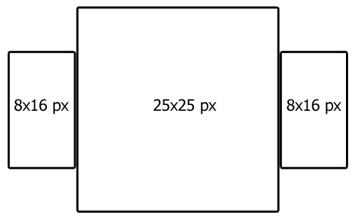
A patch with 3 different DVI fixtures should be created. In the patch plan we see a 25 x 25 pixel in the middle and a 8 x 16 pixel fixture on every side of it.
1. |
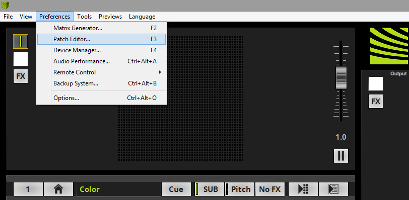
In MADRIX please go to Preferences > Patch Editor .
|
2. |
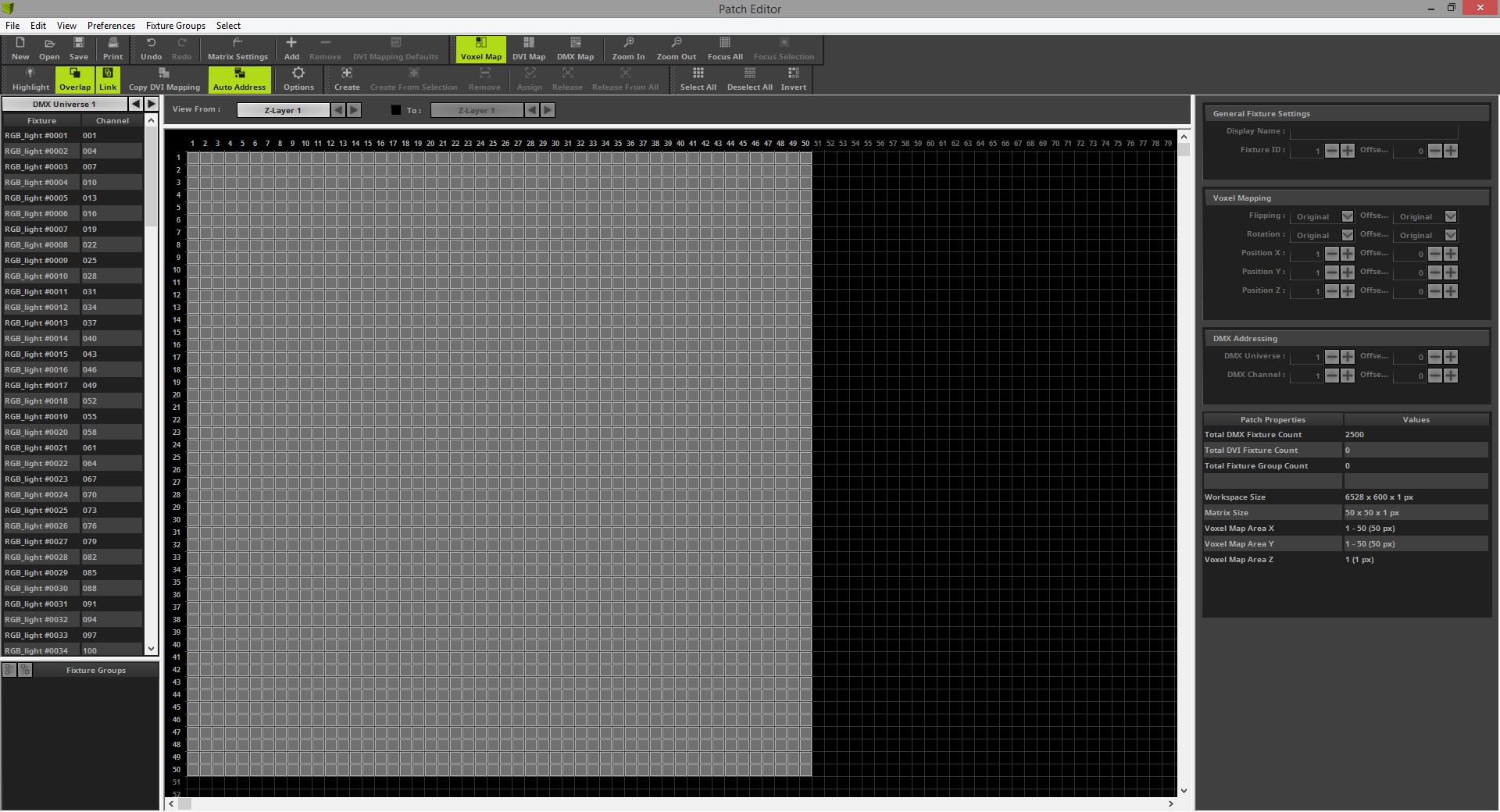
The Patch Editor opens and you will see the current patch. If you open the Patch Editor after the start of MADRIX (without any setup is loaded), you will find the default patch of 50 x 50 pixels.
|
3. |
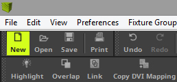
When we want to create a new patch in the Patch Editor, it is recommended to start with an empty patch. Please click the New button in the toolbar and an empty patch will be generated
|
4. |
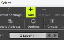
Now we can start to add the fixtures according to our patch plan. To add fixtures to the patch grid please click the Add button in the toolbar.
|
5. |
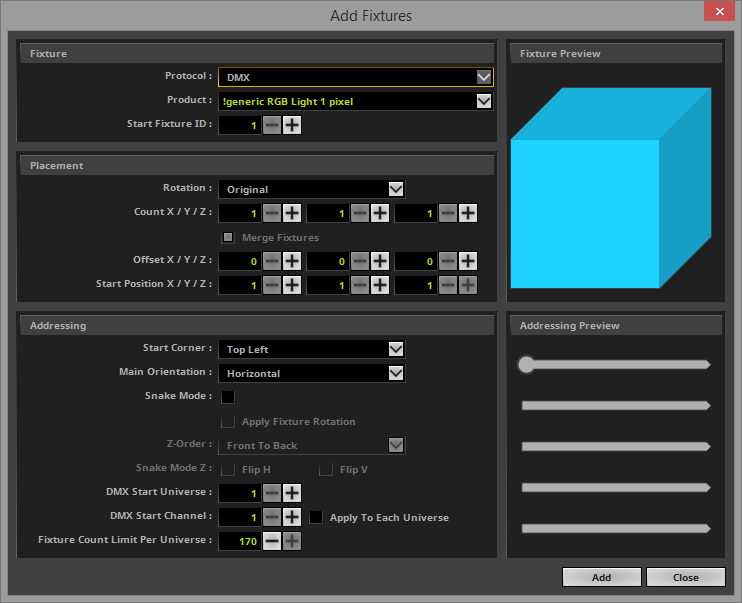
The Add Fixtures window opens the default Protocol and Product is selected when you open it the first time.
|
6. |
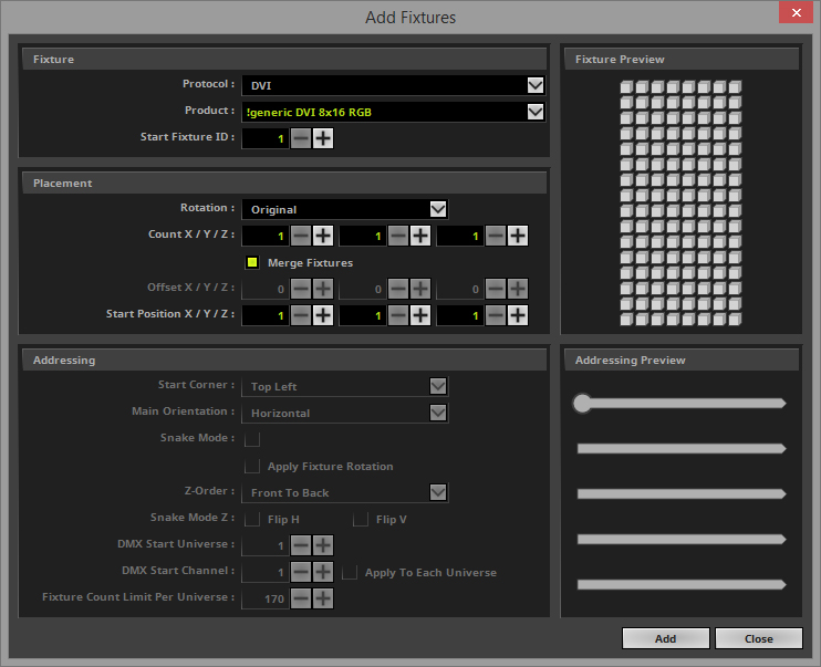
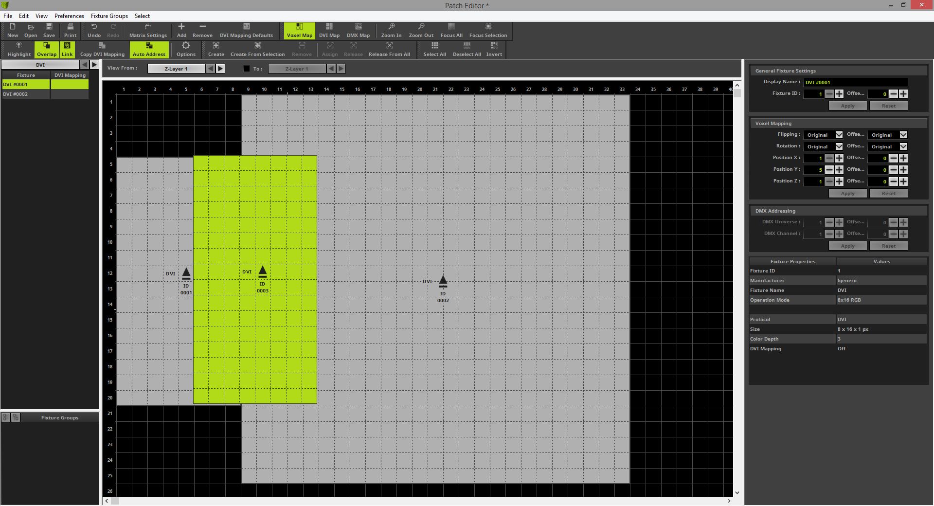
In this step we need to set the correct settings in the Add Fixtures window to add the first fixture of our patch according to the patch plan. •Protocol changed to DVI •As Product we select !generic DVI 8x16 RGB
In the Placement section we set the correct count and placement (Offset and Start Position) according to the patch plan. So we change the settings to: •Count X/Y/Z to 1 for every direction. •The Start Position X should be 1.
After we finished the settings we can click Add
|
7. |
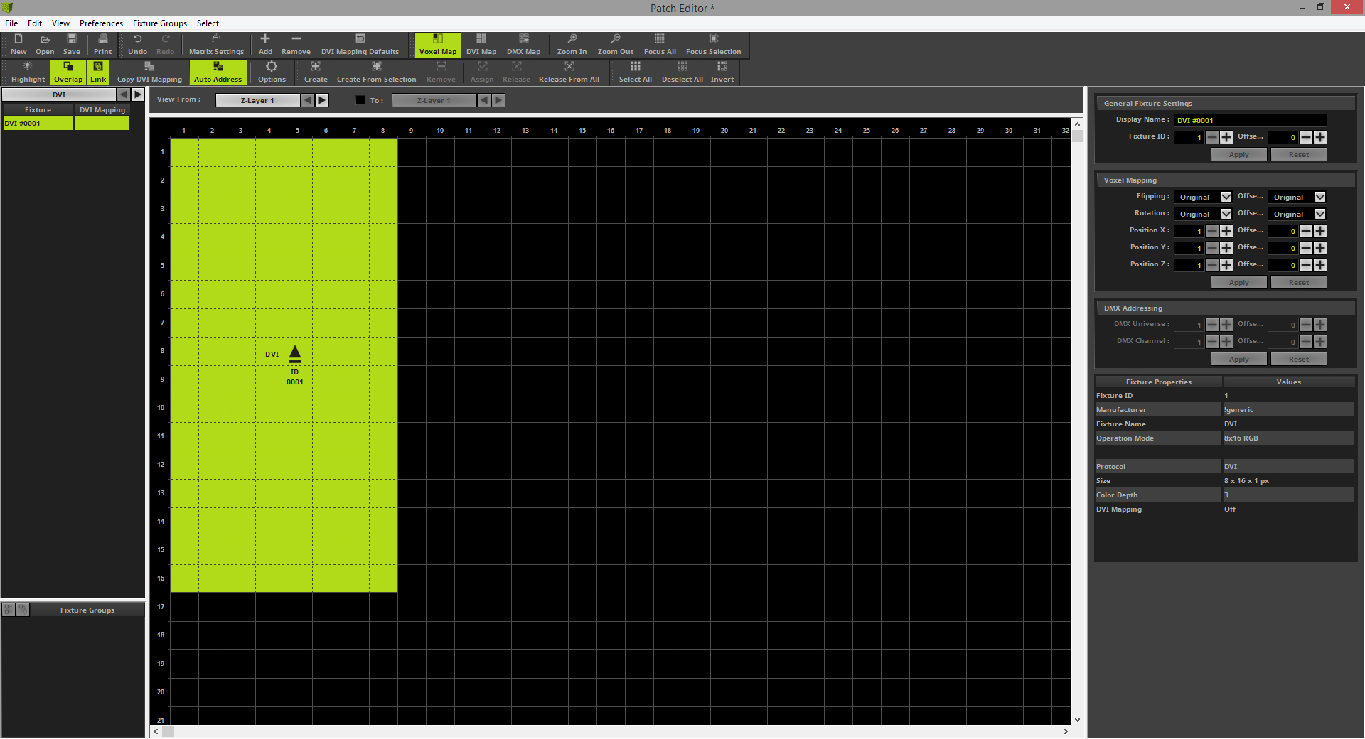
One DVI fixture with a size of 8 x 16 pixels is now added and the patch should look like in the following image.
|
8. |
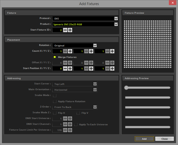
In this step we open the Add Fixtures window again and add the 25 x 25 pixels fixture. This fixture is also available as generic fixture. The fixture is located right besides the 8 x 16 pixel fixture. That means we have to patch it at Position X = 9.
In the Fixture section we don't need to change the Protocol because it it still set to DVI. •The Product we have to change to !generic DVI 25x25 RGB
In the Placement section we want to add only one of the selected fixture at Start Position X = 9, Y = 1 and Z = 1 So we change the settings to: •Start Position X to 9.
After we finished the settings we can click Add
|
9. |
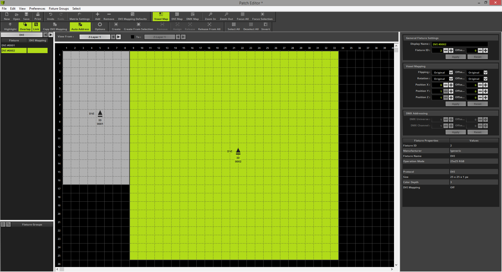
After you have add the fixtures you can see two different DVI fixtures with different resolutions in the patch grid of the Patch Editor.
|
10. |
According to the patch plan the 8 x 16 pixels fixtures is not located on the top left position. The middle point of both fixtures are at the same level. So we have to move the 8 x 16 pixels fixture. To move the fixture simply go with the mouse over the fixture and press and hold the [left mouse button] down and move it via Drag & Drop to Pixel Y = 5 for the top pixels
|
11. |
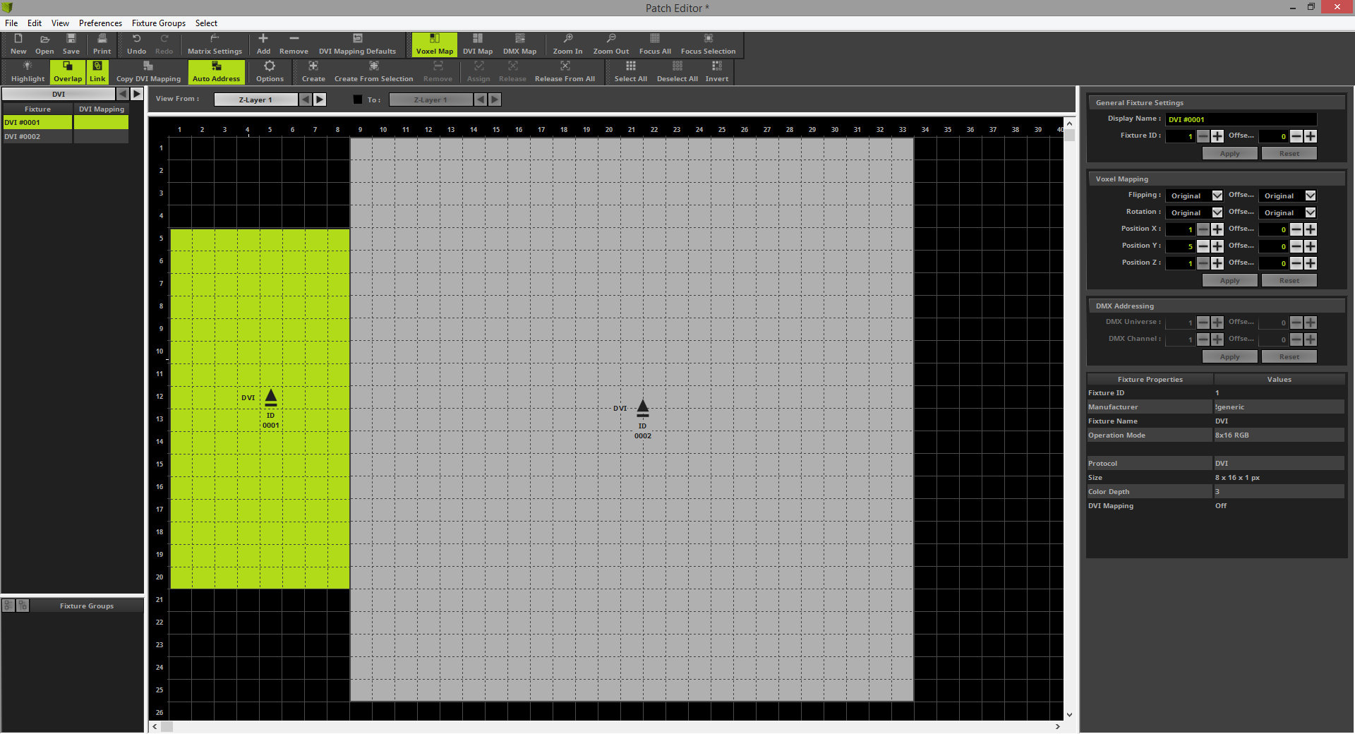
Only the 8 x 16 pixels fixture on the right side of the 25 x 25 pixels fixture is missing. Because of we have add already such a fixture we want to create a copy of this fixture. Therefor please select the 8 x 16 pixels fixture on the left side, press and hold the [Ctrl key] of your keyboard and the [left mouse button] down together. During you hold the keys down please move the mouse and you have a copy of the selected on the mouse. You can drag it to the desired position.
|
12. |
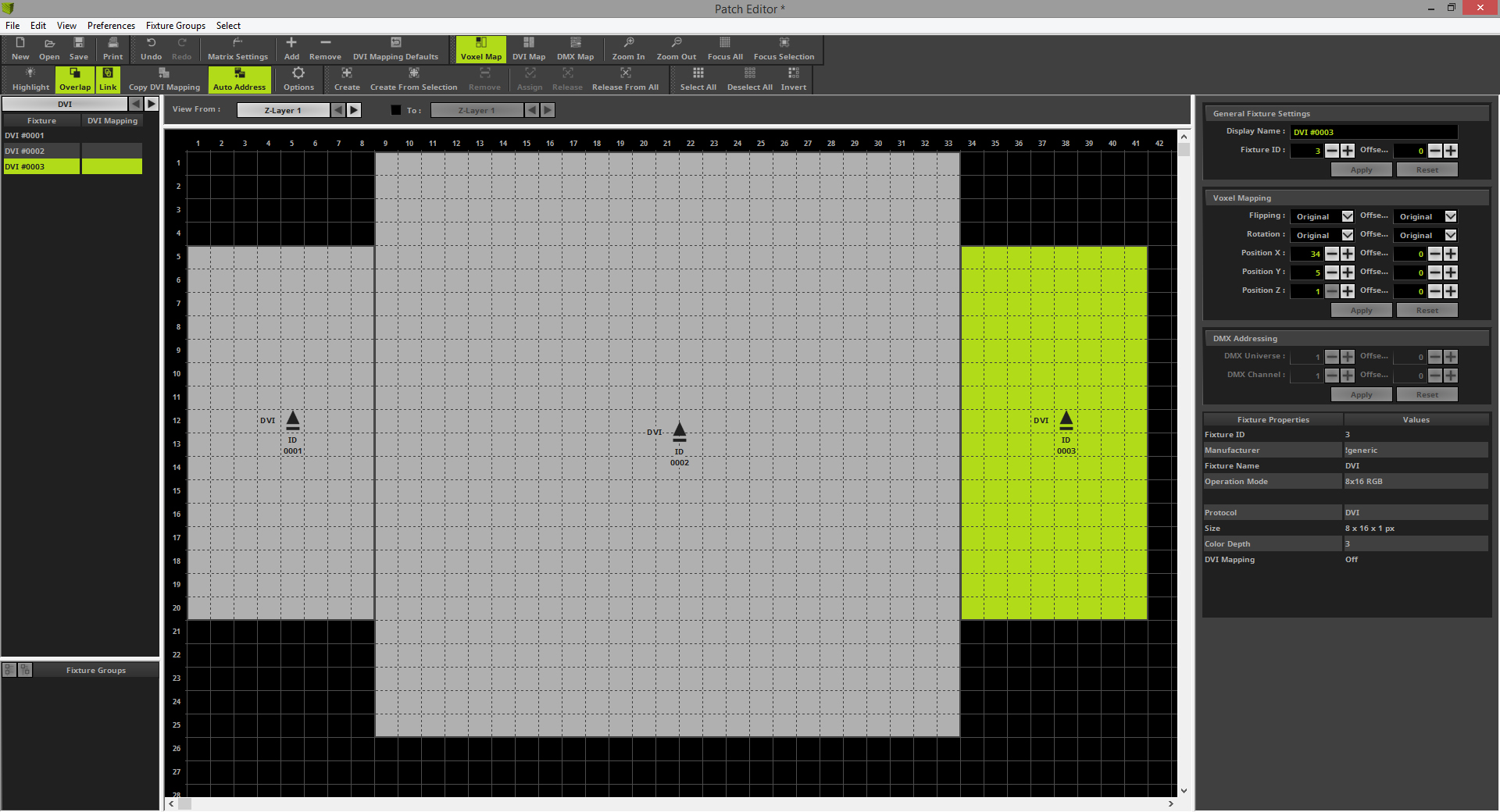
According to the patch plan we drop it at position X = 34 and Y = 5.
|
13. |
Now we only have to change the size of the Voxel Map. If you don't change the settings of the Voxel Map to the correct size, MADRIX is calculation the effect wrong.
|
14. |
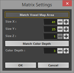
In the Matrix Settings you can easily click the Match Voxel Map Area and MADRIX is calculating the correct settings according to the created patch.
|
15. |
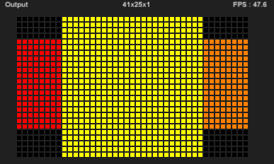
Now you can close the Patch Editor and the created patch should have a size of 41 x 25 x 1 pixels.
|
Congratulations! You have successfully learned how to create a 2D patch of different DVI fixtures with the Patch Editor.