This tutorial shows you how you can create a complex fixture with the help of the MADRIX Fixture Editor.
Date: 09/2014
MADRIX Version: 3.3 (Created with)
Note: Before you start to read this tutorial, it is recommended to read the tutorial »The MADRIX Fixture Editor
We want to create a new fixture with the following DMX chart:
Channel |
Function |
1 |
Dimmer |
2 |
Strobe |
3 |
Red 1 |
4 |
Green 1 |
5 |
Blue 1 |
6 |
Red 2 |
... |
... |
29 |
Blue 9 |
The RGB pixels of the fixture are located in 3 rows and 3 columns.
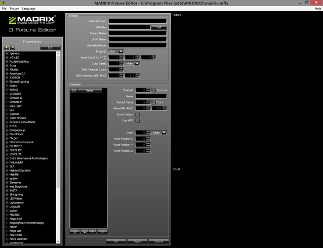
1. |
Start the Fixture Editor and load the madrix.mflx.
|
||||||||||||||||||||
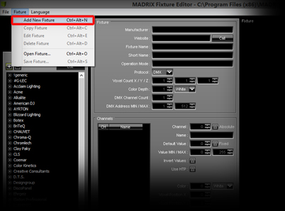
2. |
We will create a new fixture profile. Go to Fixture > Add New Fixture
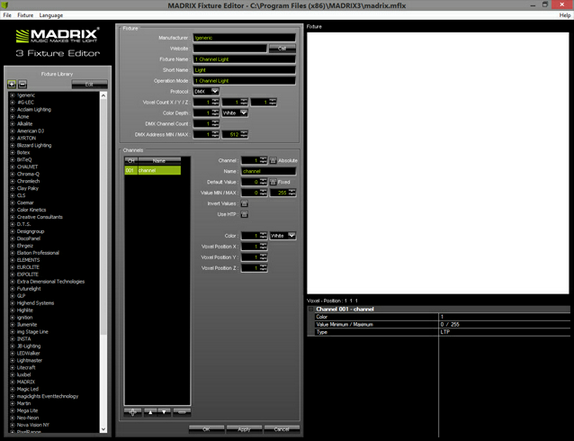
You can see that the settings are turned active and some default entries will be displayed.
|
||||||||||||||||||||
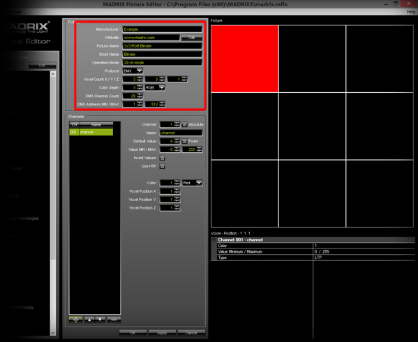
3. |
First, we have to change the fixture settings to the following: Note: For an explanation of each parameter, see the tutorial »The MADRIX Fixture Editor
|
||||||||||||||||||||
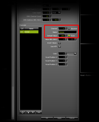
4. |
Second, we will change the settings of the first channel:
|
||||||||||||||||||||
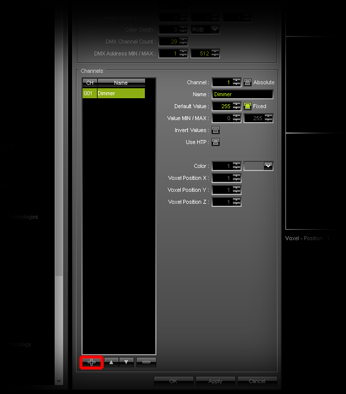
5. |
Click Add in order to add a new channel to the list.
|
||||||||||||||||||||
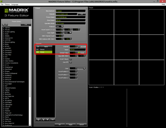
6. |
We are changing the name of the new channel to Strobe, setting the default value to 0, and enabling the option Fixed because we are not going to use the internal strobe effect of the fixture.
|
||||||||||||||||||||
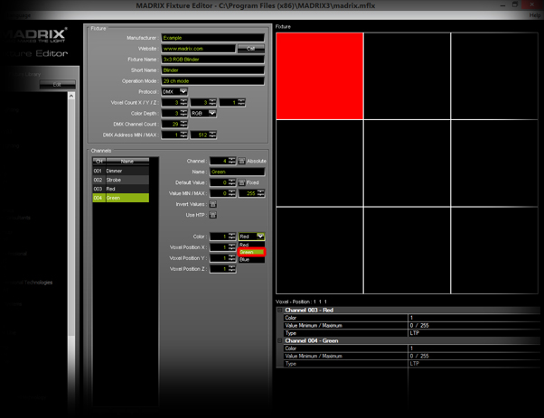
7. |
Now, click the Add button again and change the name of the third new channel to Red. Leave all other settings to their default values, because we have added the first color channel. P Repeat this step, but change the color to Blue this time. |
||||||||||||||||||||
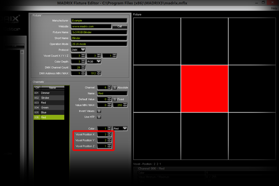
8. |
Click Add again to add channel 006. You will see that X and Y position of the voxel is increased automatically.
But in this example, the order of the pixels are positioned in rows from left to right and from up to down. Therefore, we will change Voxel Pos Y to 1. As a result, you can see that the second pixel in the first row will be used instead. |
||||||||||||||||||||
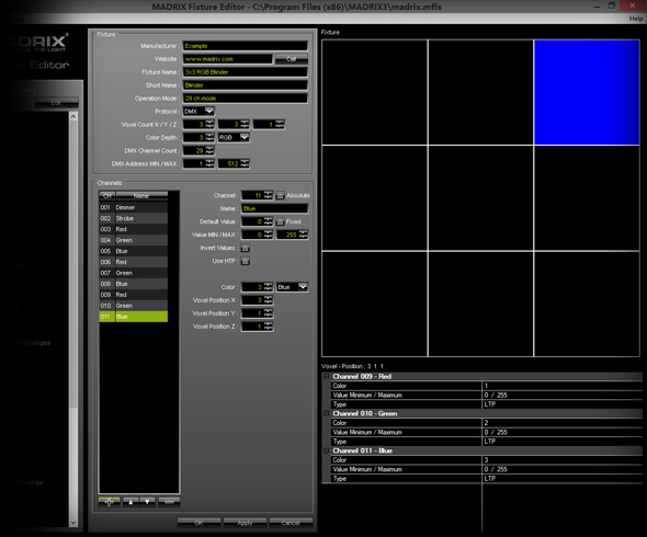
9. |
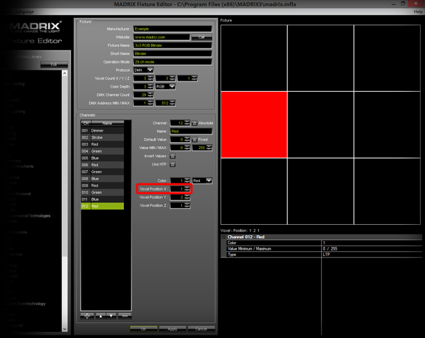
Click Add repeatedly until you have added a total of 11 channels. Now, the first row of voxels is complete.
If you click Add again, you will see that the third pixel of the second row will be activated.
But in this example, the sequence of pixels starts on the left side of each row. To change the active pixel, change Voxel Pos X to 1.
|
||||||||||||||||||||
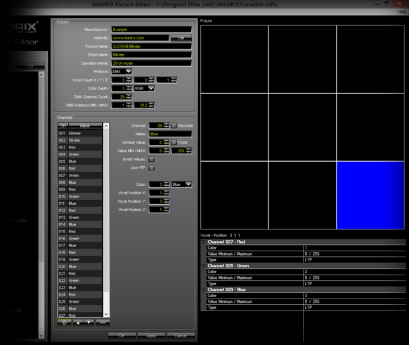
10. |
Now, you can add all the other RGB channel settings by yourself. Simply, click Add repeatedly until you have create a total of 29 channels.
|
||||||||||||||||||||
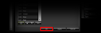
11. |
To complete the fixture creation process, click OK
|
||||||||||||||||||||
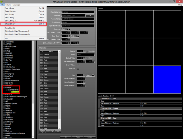
12. |
Now, you will see a new fixture branch with a new fixture in the Fixture Library section. To check if everything is correct, go to File > Check Library...
A new window will be opened. If all fixtures are created correctly, the following message appears:
|

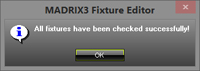
Congratulations! You have created a more complex fixture using the MADRIX Fixture Editor.