This topic includes:
▪Overview
▪Required Firmware Version
▪Using A 3rd-Party Controller
▪Putting The Device Into Operation
▪LED Status Codes
▪Remote Device Management [RDM]
▪Daisy-Chain Support
▪Reset To Factory Default Settings
▪Device Configuration
Overview
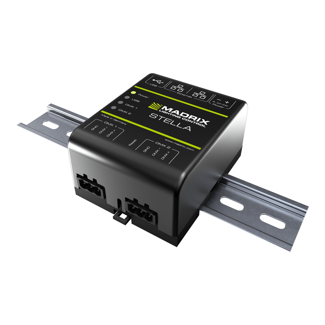
MADRIX STELLA is a 2-port network node with RDM support for solid-state projects.
The MADRIX STELLA is a dedicated control interface for DMX512 and Art-Net or Streaming ACN that is designed for high quality and practicability in permanent LED installations.
RDM Role: Transmits commands and requests to RDM Responders and back (Art-Net Node / RDM Controller)
Required Firmware Version
In order to function properly, the following firmware version is at least required for all MADRIX STELLA devices as minimum version in combination with MADRIX RADAR:
▪2.3.7261
It is recommended to always use the latest firmware version.
Using A 3rd-Party Controller
MADRIX STELLA is a standard network node. Because of this, you can use the device with applications, consoles, desks, or controllers that are compatible with Art-Net or Streaming ACN [sACN] to distribute network data via Ethernet network.
Putting The Device Into Operation
1] Connecting Your LED Fixtures/DMX Devices
Please see the MADRIX STELLA Technical Manual & Quick Start Guide on how to connect your LED fixtures/DMX devices to MADRIX STELLA.
»help.madrix.com
2] Connecting To Power And Data
Please see the MADRIX STELLA Technical Manual & Quick Start Guide on how to connect to power and data.
»help.madrix.com
3] Device Settings
Make sure to set the correct network data source and other settings according to the controller/sender you want to use.
Continue with:
▪Device Configuration
LED Status Codes
The following tables describe the LED status codes of the device.
STATUS
|
STATUS LED POWER
|
Powered off
|
Power not connected. ’ The device has no power.
|
Permanently green
|
Connected to power. ’ The power is on.
|
Blinking green
|
Bootloader activated. ’ Reset device / upload firmware.
|
STATUS
|
STATUS LED USB
|
Powered off
|
USB not connected.
|
Red +
blinking green
|
Communicating over USB.
’ Sending or receiving data over USB. The USB port works.
|
Fading between
red +green
|
Connected to USB; Drivers installed correctly.
’ No data is sent over USB.
|
Orange
|
Connected to USB; No drivers installed.
’ Reinstall software and drivers or try a different USB port.
|
STATUS
|
STATUS LED DMX 1
|
STATUS LED DMX 2
|
Powered off
|
No data is sent.
|
No data is sent.
|
Blinking green
|
Sending or receiving data.
’ The DMX port works.
|
Sending or receiving data.
’ The DMX port works.
|
STATUS
|
STATUS LEDS ETHERNET PORTS
|
Green off
|
10 MBit/s connected.
|
Green on
|
100 MBit/s connected.
|
Orange on
|
Network connected.
|
Orange blinking
|
Sending or receiving data. ’ The Ethernet port works.
|
Remote Device Management [RDM]
In order to use it, call up the built-in web configuration [see below] and go to DMX Output Settings > Enable RDM for ports DMX 1 and/or DMX 2
Make sure to disable RDM on the specific port, when using STELLA for DMX-IN.
Daisy-Chain Support
STELLA features 2 separate Ethernet network ports. Either one is fully functionally for IN and OUT and can be used for the data connection without using a separate network switch or router.
[We recommend to connect a maximum of 40 units after one another in a row, when using Art-Net in Unicast Mode or Streaming ACN Multicast at a max. data rate of 50 FPS / 20 ms without any additional devices in the network.
In the MADRIX 5 Software, we highly recommend to activate ArtSync for excellent image quality.]
Reset To Factory Default Settings
In rare cases, you might need to do a reset to factory default settings, for example to reset to the device to its default IP address as shown on the side of the device:
Reset Via Reset Button
1] Disconnect all connections from the device [power, data, DMX].
2] Use a suitable tool to press the reset button [between DMX 1 and 2].
3] Continue to press the reset button and supply power again over 'Power' or USB.
4] Continue to press the reset button and wait until all status LEDs of the device flash repeatedly or wait 10 seconds.
[Simply repeat these steps should the process fail.]
Device Configuration
When connected to Ethernet network, you can easily configure MADRIX STELLA using the built-in web configuration page.
Both, STELLA and your computer, need to be in the same network.
Using a standard web browser:
▪Connect MADRIX STELLA and your computer to the same network.
▪Assign correct network settings for your PC in the Windows operating system.
[Recommended default settings: IP address 10.0.0.1 / Subnet mask 255.0.0.0]
[Please note: Your devices and the sender, such as the PC that runs MADRIX RADAR, need to have the same subnet mask!]
▪Open your web browser and enter the IP address of MADRIX STELLA.
[You can find the default IP address on the back side of the device.]
▪The web configuration page will be launched. Now, you have access to various information and settings.
Configuration Using A Web Browser
When connected to Ethernet network, you can easily configure MADRIX STELLA using the built-in web configuration page.
You have access to the web interface. Both, STELLA and your computer, need to be in the same network.
Using a standard web browser:
▪Connect MADRIX STELLA and your computer to the same network.
▪Assign correct network settings for your PC in the Windows operating system.
[Recommended default settings: IP address 10.0.0.1 / Subnet mask 255.0.0.0]
[Please note: Your devices and the sender, such as the PC that runs MADRIX 5, need to have the same subnet mask!]
▪Open your web browser and enter the IP address of MADRIX STELLA.
[You can find the default IP address on the back side of the device.]
▪The web configuration page will be launched. Now, you have access to various information and settings.
MADRIX STELLA automatically switches to input when receiving data [DMX-IN]. Since this happens automatically, there is no need and no option to manually switch from output to input.
Please confirm any changes with Set
Device
|
Name - Allows you to change the main label of the device by entering a name. The default setting is MADRIX STELLA.
▪This refers to LongName within Art-Net with a maximum of 64 characters.
▪This refers to Source Name within sACN with a maximum of 63 characters.
▪This refers to the communication with the MADRIX 5 Software over Ethernet network or USB.
Short Name (Art-Net) - Allows you to change the ShortName identifier used by Art-Net. The default setting is the IP address of the device.
Confirm with Set
|
Network Address
|
You can change the basic network device settings.
Confirm with Set
▪IP Address
▪Subnet Mask
[Please note: Your devices and the sender, such as the PC that runs MADRIX 5, need to have the same subnet mask!] |
Network To DMX Output
|
This section shows the network settings when using the DMX ports for output [DMX 1 and DMX 2].
Confirm with Set
Assigned Network Universe - Defines the universe on which data is sent.
▪By default, universe 1 and 2 assigned to DMX 1 and DMX 2.
▪If you are broadcasting data for a large number of Universes [using Broadcast Mode instead of using Unicast Mode] with MADRIX 5 or a 3rd-party controller for example, you can assign different DMX universes to each STELLA device with these settings. Each MADRIX STELLA will then only receive data from the specific Art-Net universe and send it to its specified output port.
Example: You can set up that STELLA #1 only listens to Art-Net universe 1 and 2, while STELLA #2 listens to Art-Net universe 3 and 4, and STELLA #3 listens to Art-Net universe 5 and 6, and so on.
▪Universes are shown in hexadecimal notation and Art-Net Net switch / sub-net switch notation in the Network Universe tooltips.
Enable RDM - Allows the device to receive and send Remote Device Management data on the specific port.
▪Disable RDM on the specific port, when using STELLA for DMX-IN.
▪Only enable RDM if you wish to use it. Otherwise, disable RDM to avoid any potential issues.
RDM UID Count - Shows the number of uniquely identified RDM devices discovered and connected to the controller.
▪May change continuously during an active RDM discovery process.
Device Accepts Network Data From - Defines the data source for the device. Choose from the following options:
▪ Art-Net
▪Streaming ACN
▪Art-Net And sACN
Note: UCS512D can be controlled with MADRIX STELLA (with the RDM functionality disabled).
|
DMX Output Configuration
|
This section shows the settings for the DMX ports when used for output [DMX 1 and DMX 2].
Confirm with Set
Channel Offset - Allows you to shift the received DMX universe [512 DMX channels] per port if required.
▪This will modify the output.
▪+1 To +511 - Adding a positive channel offset will shift the received channels to higher channel numbers.
- Example: Received channel #1 will be shifted to channel #11 by using a channel offset of 10.
- That means that new channels are added to the data [in front of the received data block, with DMX value 0], while any channels that now would be higher than 512 will be removed.
- Example, continued: Channels 1 to 10 are newly added, while channels 503 to 512 are removed.
▪-1 To -511 - Adding a negative channel offset will shift the received channels to lower channel numbers.
- Example: Received channel #512 will be shifted to channel #412 by using a channel offset of -100.
- That means that the first channels will be removed. The frame will be shorter.
- Example, continued: Channels 1 to 100 are now removed and the frame has 412 channels in total.
▪Example: Your fixture should start with DMX channel 7.
- In the ideal case, you would set its DMX start address to 7.
- If your fixture somehow is set to channel 6, you could increase its start address by +1.
- Or you could shift the data that is sent by your device by -1 in order to change the data from channel #7 to channel #6.
[If you cannot change the fixture's settings or you cannot reach it anymore, for example.]
▪Please note: According to the DMX512 standard, a minimum of 21 channels will always be sent.
▪A Channel Offset can have several advantages, such as splitting a single universe onto multiple output ports.
- For example, your sender can only send on one universe and you wish to output it on two ports.
On DMX 1, you would like to send the first 150 channels and on DMX 2, you would like to send channels 151 to 300.
Then, you can set both to the same universe and set a Channel offset of 150 for DMX 2.
Channel Order - Allows you to change the order of [color] channels for the output.
▪For example, if you receive channels 1-2-3 [i.e. RGB, for example], the setting 1-2-3-(4) will send it out as R-G-B. In contrast, the setting 3-2-1 would send B-G-R. [Please only change this setting when needed and when using simple, standard fixtures with RGB or RGBW, for example.]
Send Full Frames - Activates that always 512 channels will be sent out.
▪512 channels are sent per frame even if the data that is received by the device includes less than 512 channels for this port and universe.
▪The device automatically sends values of 0 on channels that are not used.
Output Intensity - Sets the brightness level of the output towards the LEDs by functioning as a dimmer.
▪For example, when the device receives a DMX value of 255 on a channel, this would be dimmed to 127 when the Output Intensity is set to 50 %.
▪The minimum value is 1 %. The default value is 100 %.
▪Can be used alone or at the same time as Upper Intensity Limit. First, the device applies the Output Intensity. Second, the Upper Intensity Limit is applied.
Upper Intensity Limit - Sets the maximum brightness level that can be sent.
▪The minimum value is 1 %. The default value is 100 %.
▪Can be used alone or at the same time as Output Intensity. First, the device applies the Output Intensity. Second, the Upper Intensity Limit is applied.
In Case Of Missing Network Data - Allows you to specify the output settings should the device not receive data for a specified DMX universe [in both cases, when having never received data in the first place or when the data is not being received anymore and a timeout is reached]. Choose from the following options:
▪Send The Last Received Frame Continually
[Is true when data is not being received anymore and a timeout is reached.]
[If no data is received at startup, black frames will be sent.]
▪Send Black Frames Continually
[Is true when data is not being received anymore and a timeout is reached.]
[If no data is received at startup, black frames with value 0 will be sent.]
▪Send White Frames Continually
[Is true when data is not being received anymore and a timeout is reached.]
[If no data is received at startup, white frames with value 255 will be sent.]
▪Stop Sending After Sending A Black Frame
[Is true when data is not being received anymore and a timeout is reached.]
[If no data is received at startup, black frames will be sent.]
▪Stop Sending
[Is true when data is not being received anymore and a timeout is reached.]
[If no data is received at startup, there is also no output.]
Select this option if you wish to use DMX-IN! |
DMX Input To Network
|
This section allows you to specify settings for DMX input, which is sent out to the network from the device.
Confirm with Set
When data is received, MADRIX STELLA will automatically forward it to Ethernet network.
The device automatically switches to input when receiving data via the DMX ports [DMX-IN].
- Since this happens automatically, there is no need and no option to manually switch from output to input.
- Make sure to 1] disable RDM and 2] set the option In Case Of Missing Network Data to Stop Sending.
If both output and input are sent to the device, the device will activate the output.
Send Universe To Network - STELLA can receive 512 channels per port. This setting defines on which universe those 512 channels are sent.
▪By default, 256 is set for DMX 1 and 255 is set for DMX 2.
▪Valid values range from 1 to 32768.
Always Send Full Frames To Network - Activates that always 512 channels will be sent out.
▪512 channels are sent per frame even if the data that is received by STELLA includes less than 512 channels for this port and universe.
▪STELLA automatically sends values of 0 on channels that are not used.
▪Art-Net Broadcast Mode - Sends Art-Net data to all IP addresses in the network.
▪Art-Net Unicast Mode - Sends Art-Net data only to one recipient, e.g. your MADRIX computer. Enter the IP address of your receiver here.
▪sACN Multicast Mode - Sends Streaming ACN data to IP address 239.255.1.0 for port 1 and to IP address 239.255.0.255 for port 2. |
Special Commands
|
Reboot - Reboot System - Restarts the device completely. [The website will automatically be reloaded after a few seconds.]
Reset - Reset To Factory Default Settings - Restores the original settings of the device. [Since this may change back the IP address to the original setting, the website will automatically be reloaded after a few seconds and you will automatically be redirected to the correct website and IP address.]
|
Device Information
|
▪Model
[The device type.]
▪IP Address
[The current IP address. Can be used as a click-able link to call the device with this IP address.]
▪NetBIOS
[An alternate way to call up the web configuration or find the device in the network, and without using the IP address. Can also be used as a click-able link to call the device with its NetBIOS name. Main workflow: Assuming correct network settings, simply type http://SERIALNUMBER/ into your web browser, such as http://STELLA000601/ ; often merely STELLA000601/ should work. If you want to ping the device, use only STELLA000601]
▪MAC Address
[A permanent, unique address.]
▪Serial Number
▪Firmware
[The current firmware version.]
▪Bootloader
[The current bootloader version.]
▪Hardware
[The hardware revision.]
▪External Voltage
[The current voltage for External Power.]
▪System Temperature
[The current ambient temperature inside the device case.]
▪Ethernet
[The current status of the two Ethernet ports.]
▪Up Time
[The time that has passed since the last power-cycle or restart.] |
|