This topic includes:
▪Configuration Using A Web Browser
Configuration Using A Web Browser
When connected to Ethernet network, you can easily configure MADRIX NEBULA using the built-in web configuration page.
You have 2 options to access the web interface. Both, NEBULA and your computer, need to be in the same network.
A] Using a standard web browser:
▪Connect MADRIX NEBULA and your computer to the same network.
▪Assign correct network settings for your PC in the Windows operating system.
[Recommended default settings: IP address 10.0.0.1 / Subnet mask 255.0.0.0]
[Please note: Your devices and the sender, such as the PC that runs MADRIX 5, need to have the same subnet mask!]
▪Open your web browser and enter the IP address of MADRIX NEBULA.
[You can find the default IP address on the back side of the device.]
▪The web configuration page will be launched. Now, you have access to various information and settings.
B] Using the MADRIX 5 Software:
▪Connect MADRIX NEBULA and your computer to the same network.
▪Assign correct network settings for your PC in the Windows operating system.
[Recommended default settings: IP address 10.0.0.1 / Subnet mask 255.0.0.0]
[Please note: Your devices and the sender, such as the PC that runs MADRIX 5, need to have the same subnet mask!]
▪Go to the menu Tools > MADRIX Device Configuration...
[Keyboard shortcut: Ctrl+Alt+L]
▪Select your MADRIX NEBULA device in the list.
▪Click 
▪Your default web browser will open and the web configuration page will be launched. Now, you have access to various information and settings.
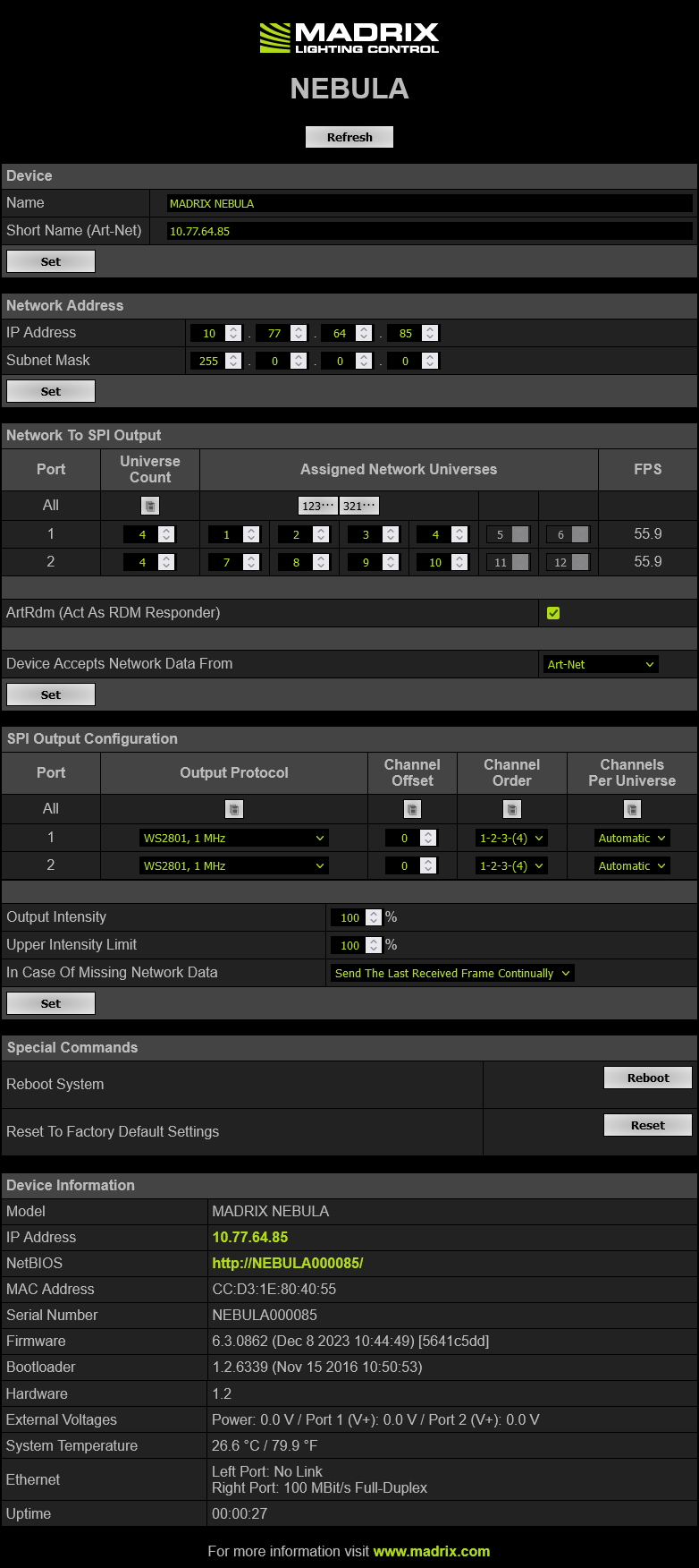
Device |
Name - Allows you to change the main label of the device by entering a name. The default setting is MADRIX NEBULA. ▪This refers to LongName within Art-Net with a maximum of 64 characters. ▪This refers to DEVICE_LABEL within RDM with a maximum of 32 characters. ▪This refers to Source Name within sACN with a maximum of 63 characters. ▪This refers to the communication with the MADRIX 5 Software over Ethernet network or USB. Short Name (Art-Net) - Allows you to change the ShortName identifier used by Art-Net. The default setting is the IP address of the device. Confirm with Set |
Network Address |
You can change the basic network device settings. ▪IP Address ▪Subnet Mask |
Network To SPI Output |
This section shows specific settings for the output ports [Port 1 and Port 2]. ▪You can set the value separately for each of the two ports. ▪You can disable universes of the port by lowering the number. ▪Firmware ≤ 5.XX: A maximum of 4 universes/minimum of 1 universes can be sent per port. The default value is 4. ▪Firmware ≥ 6.00: A maximum of 6 universes/minimum of 1 universes can be sent per port. The default value is 4. ▪Note: The fewer universes are assigned, the less data needs to be processed, and the higher the output frame rate can be. ▪Note: An output frame rate by the device of at least 33 FPS is recommended for smooth visuals. Learn more below: FPS. ▪ Assigned Network Universes - Defines the assignment of universes. ▪By default, universes 1 - 4 are assigned to Port 1, and universes 5 - 8 are assigned to Port 2. ▪If you are broadcasting data for a large number of Universes [using Broadcast Mode instead of Unicast Mode] with MADRIX 5 or a 3rd-party controller, you can assign different DMX universes to each device with these settings. Each MADRIX NEBULA will then only receive data from the specific universe and send it to its specified output port. ▪Example: You can set up that NEBULA #1 only listens to universe 1 - 8, while NEBULA #2 listens to universe 9 - 16, and NEBULA #3 listens to universe 17 - 24, and so on. ▪ FPS - Shows the possible output frame rate that can be achieved with the current settings per port (as they are set in the web configuration). ▪Not recommended: ≤ 32 FPS ▪Recommended: ≥ 33 FPS ▪Best performance: 100 Settings — The shown FPS is being calculated according to the following settings: ▪Number Of Assigned Network Universes Per Port ▪Output Protocol ▪Frequency Of The Output Protocol Data Input — The actual live output depends on the data sent to the device: ▪Art-Net/sACN over network allow for the highest data rates, unlike USB. ▪If the received data rate (sent to the device from your control software or console, for example) is lower than the calculated FPS, the actual output frame rate will also be lower (FPS then represents a maximum value). ▪If less universes are received than are assigned, the actual output frame rate could be higher in practice (FPS then represents a minimum value). ▪If the received data rate is higher than the calculated FPS, the actual output frame rate will be capped (FPS then represents a maximum value). ▪If the network source is missing, the functionality of In Case Of Missing Network Data becomes active with its different options and ways of functioning (FPS then represents a maximum value).
Device Accepts Network Data From - Defines the data source for the device. Choose from the following options: ▪ Art-Net ▪Streaming ACN ▪Art-Net And sACN |
SPI Output Configuration |
Output Protocol - In order to put MADRIX NEBULA fully into operation, it is necessary to set the correct output protocol according to the LEDs you have connected. You can set it up here. ▪Choose a signal frequency according to the specifications of your LEDs. ▪ If you do not have this information, choose a signal frequency that works for your LEDs. If the refresh rate is set too high, you will usually notice that your LEDs flicker uncontrollably. If that is the case, choose a lower frequency. ▪Certain LEDs need to be addressed first. If your LEDs need to be addressed and have not been addressed yet, please address them first. See Please Note Regarding LEDs That Need Be Addressed First below. ▪
Channel Offset - Allows you to shift the received universes [2048 DMX channels] per port if required. ▪This will modify the output. ▪+1 To +511 - Adding a positive channel offset will add another universe before the first universe ▪-1 To -511 - Adding a negative channel offset will shift the received channels to lower channel numbers. ▪
Channel Order - Allows you to change the order of [color] channels for the output. ▪Defines how received channels are newly ordered. ▪Example 1: If you receive channels 1-2-3 [i.e. RGB, for example], the setting 1-2-3-(4) will send it out as R-G-B. In contrast, the setting 3-2-1 would send B-G-R [which means that received channel 3 is put out on position 1, received channel 2 is put out on position 2, and received channel 1 is put out on position 3.] ▪Example 2: If you set 4-1-2-3, received channel 4 is put our first. Received channel 1 is put out second. Received channel 2 is put out third. Received channel 3 is put out fourth. ▪
Channels Per Universe - Allows you to define how many DMX channels are sent per DMX universe for each port. This option enables you to adjust the device settings to the controller and LEDs you are using. Automatic - The number of channels that is received is also sent out. This is the default value. This is also the recommended setting when using NEBULA in combination with the MADRIX 5 Software. ▪1 - 512 - Limits the number of output channels to this value. If your controller sends more channels than set up here, any channels that are higher than this value will be discarded. If your controller sends fewer channels, NEBULA will fill up the rest of the channels with values of 0 [Black]. ▪Using RGB LEDs: 170 RGB LEDs can be controlled with one single DMX universe. That means a maximum of 510 DMX channels is used. Depending on your controller [please see below], the recommended setting is Automatic or 510. ▪Using RGBW LEDs: 128 RGBW LEDs can be controlled with one single DMX universe. That means a maximum of 512 DMX channels is used. Depending on your controller [please see below], the recommended setting is Automatic or 512. ▪Using 1-channel LEDs: 512 single color LEDs can be controlled with one single DMX universe. That means a maximum of 512 DMX channels is used. Depending on your controller [please see below], the recommended setting is Automatic or the number of LEDs used. ▪Using MADRIX 5: By default, MADRIX 5 sends optimized frames as set up in the Device Manager. That means according to the number of channels used by the fixtures and Patch, MADRIX 5 and then NEBULA will send out the correct number of channels to the LEDs. ▪Using a 3rd-party controller: When your controller is only able to send full frames [which means that it always sends 512 DMX channels per single frame], it is recommended to set up a specific value here as described above in order to correctly work with MADRIX NEBULA and your LEDs. Recommendation: If using RGB LEDs, set up 510 channels per universe. ▪
Output Intensity - Sets the brightness level of the output towards the LEDs by functioning as a dimmer. ▪For example, when the device receives a DMX value of 255 on a channel, this would be dimmed to 127 when the Output Intensity is set to 50 %. ▪The minimum value is 1 %. The default value is 100 %. ▪Can be used alone or at the same time as Upper Intensity Limit. First, the device applies the Output Intensity. Second, the Upper Intensity Limit is applied. Upper Intensity Limit - Sets the maximum brightness level that can be sent. ▪The minimum value is 1 %. The default value is 100 %. ▪Can be used alone or at the same time as Output Intensity. First, the device applies the Output Intensity. Second, the Upper Intensity Limit is applied.
In Case Of Missing Network Data - Allows you to specify the output settings should the device not receive data for a specified DMX universe [in both cases, when having never received data in the first place or when the data is not being received anymore and a timeout is reached]. Choose from the following options: ▪Send The Last Received Frame Continually ▪Send Black Frames Continually ▪Send White Frames Continually ▪Stop Sending After Sending A Black Frame ▪Stop Sending |
RDM |
ArtRdm (Act As RDM Responder) - Enables ArtRdm to be able to reply to RDM requests by an RDM controller as an RDM responder over Art-Net with status and sensor data. This enables monitoring of the device via MADRIX RADAR. The option is disabled by default. ▪Input Voltage [Power] ▪Port 1 Voltage ▪Port 2 Voltage ▪USB Power ▪Temperature ▪Device Model [incl. Hardware Revision] ▪Software Version [of the Firmware and Bootloader] ▪And device information, such as IP Address, Device Short/Long Name, etc. ▪Learn more Using RDM And MADRIX RADAR |
Special Commands |
Reboot - Reboot System - Restarts the device completely. [The website will automatically be reloaded after a few seconds.] Reset - Reset To Factory Default Settings - Restores the original settings of the device. [Since this may change back the IP address to the original setting, the website will automatically be reloaded after a few seconds and you will automatically be redirected to the correct website and IP address.] |
Device Information |
▪This section displays various details about the device, including: ▪Model ▪IP Address ▪NetBIOS ▪MAC Address ▪Serial Number ▪Firmware ▪Bootloader ▪Hardware ▪External Voltages ▪System Temperature ▪Ethernet ▪Up Time |
Please Note Regarding LEDs That Need Be Addressed First
Certain LEDs need to addressed first. Please check the below table to see if your LEDs might need to be addressed.
▪If they are already addressed with another tool, you do not need to address them again.
▪If your LEDs are not yet addressed, please address them:
1. Connect your LEDs. Learn more »Putting The Device Into Operation
2. Connect to power and data. Learn more »Putting The Device Into Operation
3. Choose the corresponding Addressing Protocol as Output Protocol of the MADRIX NEBULA. Confirm with 'Set'. You only have to do this once for your each LED tape.
4. Once your LEDs are addressed, continue by selecting the correct Output Protocol according to your LEDs.
LED |
Addressing Protocol |
▪WS2821 |
▪Choose the Addressing Protocol 'WS2821 Addressing' in order to address your LEDs. |
▪WS2822S |
▪Choose the Addressing Protocol 'WS2822S Addressing' in order to address your LEDs. |
| MADRIX NEBULA User Manual 6.11. |
| [Ctrl & +/-] = Zoom In/Out | [Ctrl & 0] = 100% |
|
Previous Next
|
|
Enable Automatic Translation | Activer La Traduction Automatique | 启用自动翻译 |