In this tutorial you will learn how to create a combined 2D patch which consists of DMX and DVI fixtures.
Date: 10/2018
MADRIX Version: 5.0 (Created with)
Corresponding Video Tutorial: »Creating A 2D Patch For DMX & DVI Output With The Patch Editor
Task:
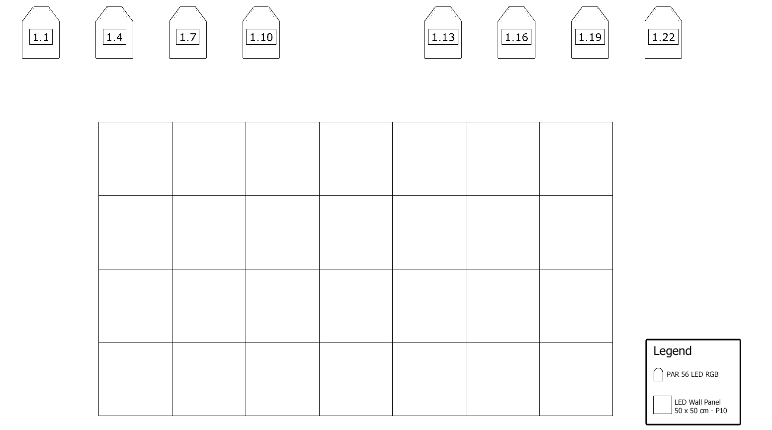
In this tutorial we will create a patch consisting of 8 LED PAR 56 RGB and a P10 DVI Wall with a resolution of 50 x 50 pixels per element.
1. |
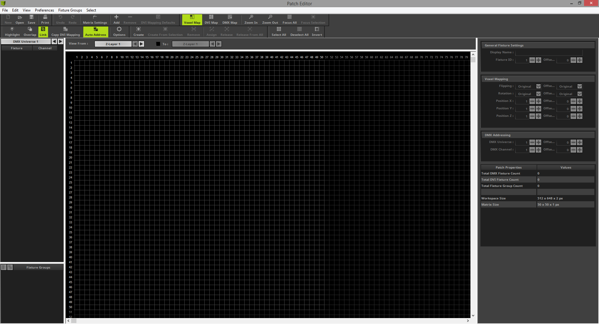
We will start with an empty patch. So please open the Patch Editor and create a New patch. If you don't know how to create an empty patch in MADRIX 5, please have a look at the following tutorial:
|
2. |
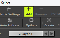
Now we can start to add the fixtures according to our patch plan. To add fixtures to the patch grid please click the Add button in the toolbar.
|
3. |
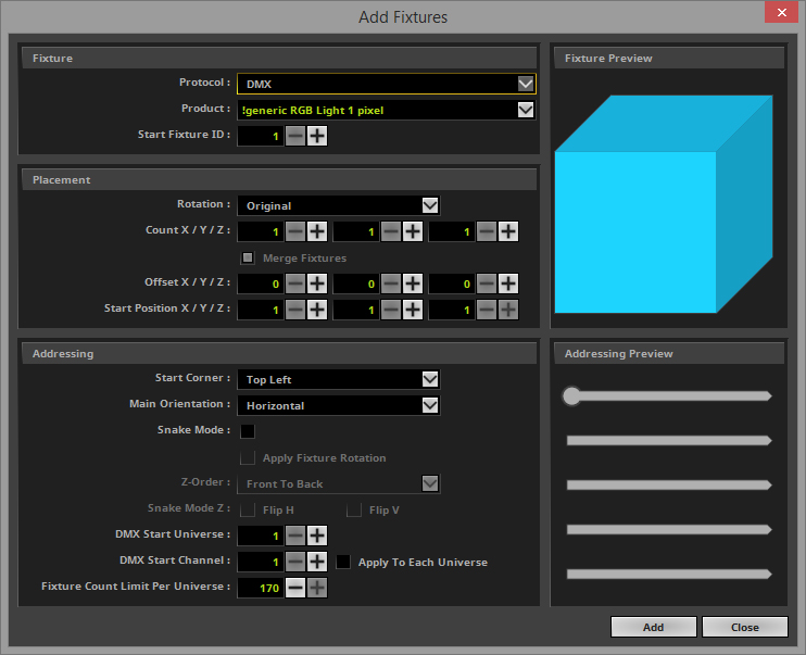
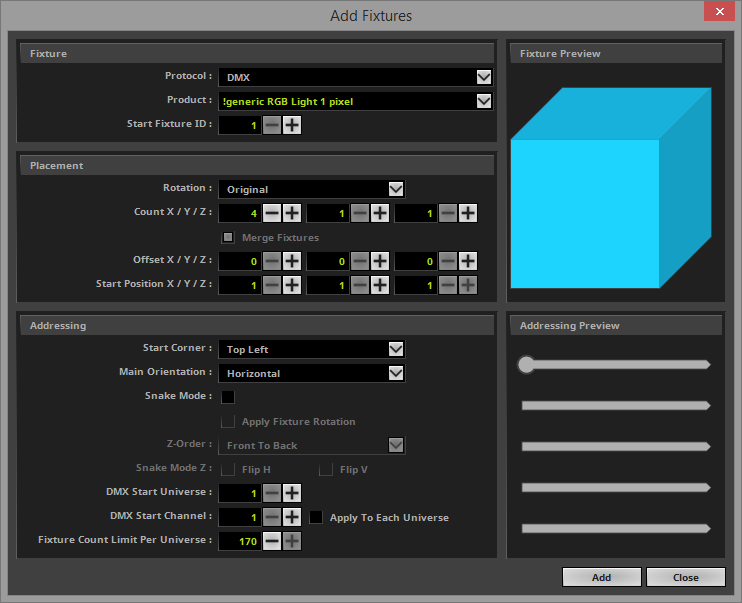
The Add Fixtures window opens. When opening the first time the default Protocol and Product is selected when you open it the first time.
|
4. |
We can start to add the fixtures according to our patch plan. •DMX as Protocol •!generic RGB Light 1 pixel as Product
In the Placement section we want to select the correct fixture count according to the patch plan. •Count X to 4. We don't need to change the Count Y and Z. It should be 1.
In the Addressing section we don't have to change a setting this time. According to our patch plan we start on DMX Universe 1 with DMX Start Channel 1 and the address assignment is from left to right. After we finished the settings we can click Add
|
5. |
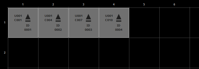
Now you can see there are 4 fixtures patched on the left side.
|
6. |
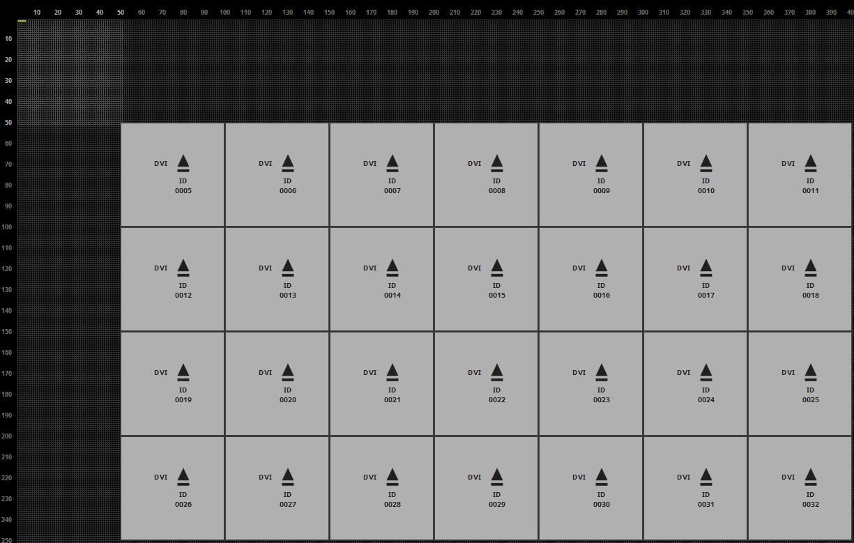
In this step we want to add the fixtures which are responsible for the DVI output. Therefor please open the Add Fixtures window again. •Protocol changed to DVI •As Product we select !generic DVI 50x50 RGB
In the Placement we set the correct count, the Offset between fixtures and the Start Position according to the patch plan. So we change the settings to: •Count X to 7 and Count Y to 3. •The Start Position X should be 50 and also the Start Position Y should be 50.
After the previous changes we have finished the settings in the "Add Fixtures" section and now we can click Add.
|
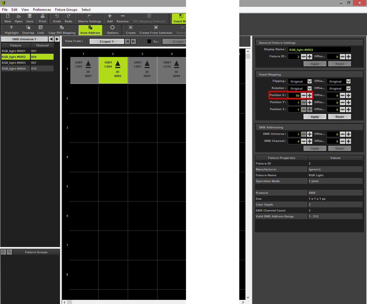
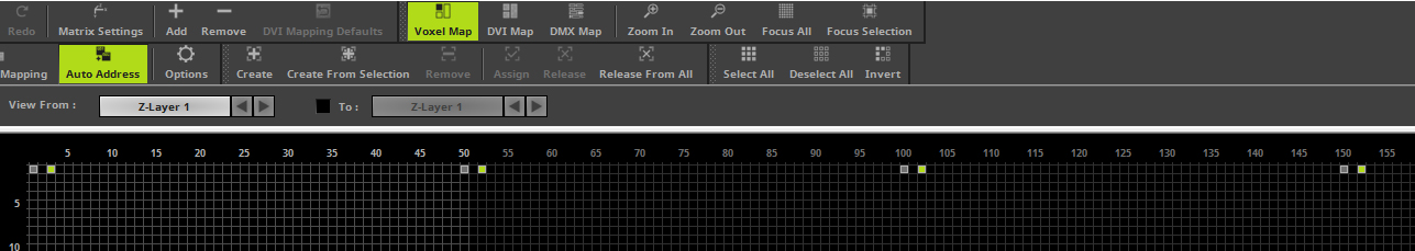
We would like to work with a pixel exact mapping. For this reason we have to move our added DMX fixtures according to our patch plan. So we have to relocate the fixture with the Fixture ID 2 to position 50, fixture with the Fixture ID 3 to 100 and the one with the Fixture ID 4 to position 150. To change the position of a fixture please select the desired fixture and navigate to the Voxel Mapping section of the Settings on the very right side of the Patch Editor. After you have set the desired value you have to click Apply.
|
|
8. |
In this step we want to add the 4 PAR cans,which are located on the right side next to the DVI fixtures. For this task we want to copy the 4 already added PAR cans. To copy the 4 PAR cans we select all 4 fixtures. You can easily select the fixtures when you press and hold the [Shift key] + [left mouse button] down, now please create a bounding box around the desired fixtures. When you now release the [mouse button], the fixtures in the bounding box are selected. When you now press and hold the [Ctrl key] + [left mouse button] while having one of the fixtures selected, a copy of the fixtures will be created when you [move] the mouse.
|
9. |
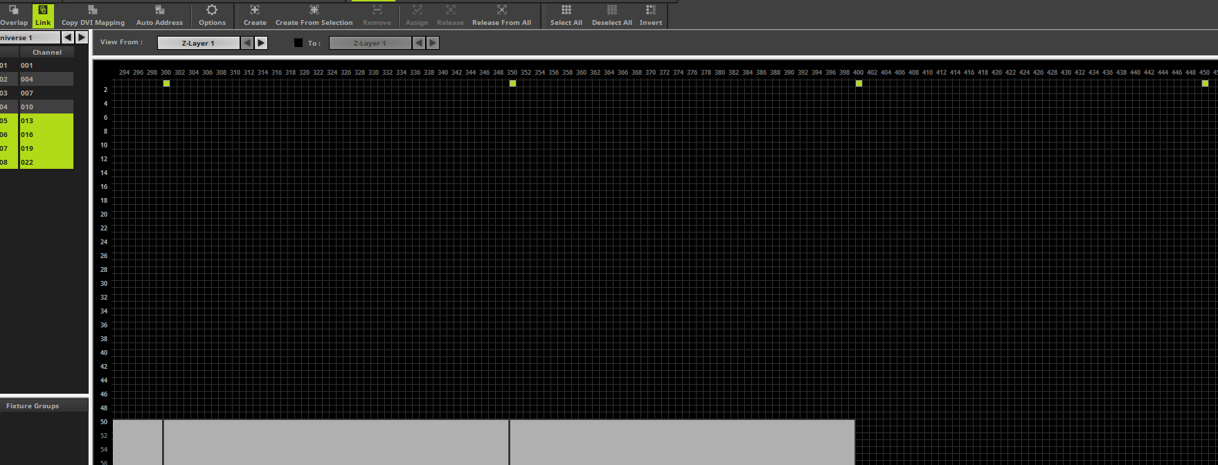
As explained in Step 7 we want to work pixel exact. That means we have to adjust the correct positions for the copied fixtures, too. According to the patch plan we have to move the PAR cans on the right side to pixel Position X = 300, 350, 400 and 450. The Y position is always 1. Because we have copied the 4 fixtures with the correct offset and the fixtures are still selected we can easily move all fixtures together to the correct position.
|
10. |
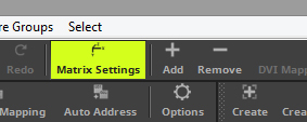
In this step we have to set the correct matrix size. Please open the Matrix Settings window via the toolbar.
|
11. |
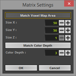
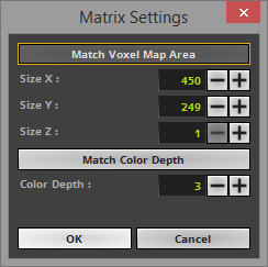
After you opened the Matrix Settings you will see the current set Size and Color Depth. It is important to set the matrix size and color depth to the correct value. Otherwise MADRIX will calculate the effects wrong.
|
12. |
The easiest way to set the correct matrix size and color depth is by using the Match Voxel Map Area and Match Color Depth buttons. After you press the buttons the Matrix Settings will be changed automatically. After a click at the OK button the settings will be accepted.
|
13. |
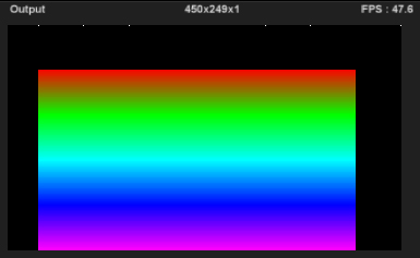
When we now close the patch and have a look at one of the MADRIX previews, our patch as the correct size. At the top line we will find 8 Par cans and a DVI screen below.
|
Congratulations! You have created a combined patch of DMX and DVI fixtures.