This topic includes:
You can resize, reposition, and further modify every MADRIX Effect; independently of your configuration in the Matrix Generator or Patch Editor.
By default, every Layer [i.e. every MADRIX Effect] is shown on the complete virtual LED matrix [Matrix Size]. It is mapped to the complete LED installation. You can change that.
| ▪ | Click Map |
![]()
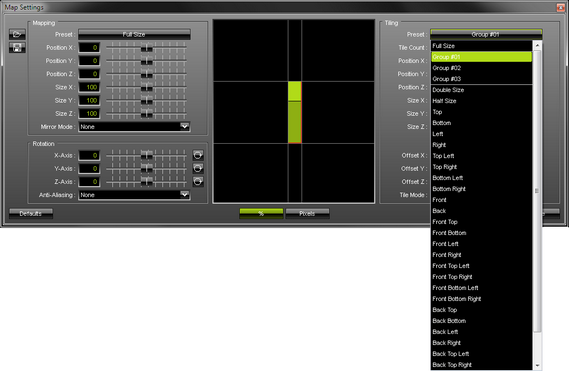
| ▪ | A new window will open [in 2D or 3D view according to the Matrix Size]. |
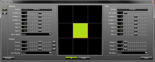

![]() Before you start making any changes, choose between relative values in percent [%] or absolute values in pixels [Pixels].
Before you start making any changes, choose between relative values in percent [%] or absolute values in pixels [Pixels].
The Map Effect window has 4 sections:
| ▪ | and a graphical overview showing you the consequences of your changes. - You will see a graphical 2D or 3D model of the virtual LED matrix. - Because you can change the size and position of a Layer, the graphical model will change accordingly. - Various guidelines referring to all edges of the graphical model will help you with the perspective [e.g., through parallel shift]. - You can also use the mouse to position the graphical model. - The graphical model represents your virtual LED matrix, which is your LED installation. |
| ▪ | All 3 options can be used in combination [Mapping / Rotation / Tiling]. |
| ▪ | All 3 options are powerful ways to customize visuals. |
| ▪ | All options refer to the virtual LED matrix [Matrix Size] you have configured in the Matrix Generator or Patch Editor. |
| ▪ | You can save Map Settings to an external file or load previously saved settings from an external file. Learn more Saving And Loading |
| ▪ | Click Defaults to cancel any changes and restore the default settings. |
| ▪ | Click Close to close the window. |
Mapping allows you to change the size and position of a Layer.
In this way, you can assign different MADRIX Effects to different areas of your LED installation [and also different fixtures].
| ▪ | Preset - Instead of adjusting the below values manually, you can decide to use these presets. MADRIX will then automatically adjust the above settings accordingly. The default value is Full Size. |
| ▪ | Position X - Defines the horizontal position of the Layer. |
| ▪ | Position Y - Defines the vertical position of the Layer. |
| ▪ | Position Z - Defines the position of the Layer in the depth. |
| ▪ | Size X - Defines the horizontal size of the Layer. |
| ▪ | Size Y - Defines the vertical size of the Layer. |
| ▪ | Size Z - Defines the size of the Layer in the depth. |
| ▪ | Mirror Mode - Mirrors the Layer [flipping]. You can choose to not apply mirroring [None], to mirror horizontally [Mirror H], vertically [Mirror V], regarding the depth [Mirror D], or in any combination [e.g., Mirror HVD]. The default value is None. |
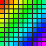
| ▪ | Set up a virtual LED matrix of 100 x 100 x 1. |
| ▪ | Create 2 Layers. |
| ▪ | For Layer 1, choose SCE Plasma and the preset Left in the section Mapping |
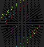
| ▪ | For Layer 2, choose SCE Wave / Radial and the preset Right in the section Mapping |
| ▪ | The result could look like this: |
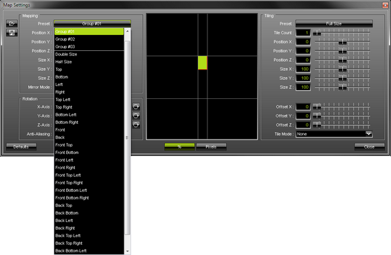
Using Fixture Groups As Mapping Preset
Fixture groups, when configured in the Patch Editor, are available as presets for Mapping and Tiling.
Learn more »Fixture Groups [Group Control]
1] Go to Mapping > Preset
- When your Patch includes Fixture Groups, as configured in the Patch Editor, the list of presets will include an item for each fixture group you have created. You will see the fixture group's Display Name.
- You will find these items below Full Size
2] Select the fixture group from the list.
3] MADRIX will automatically set the correct settings.
- The Mapping will be set according to the fixture group.
- The adjusted Map Settings will always be a rectangular selection. MADRIX uses the bounding box of the fixture group with its largest dimensions in X, Y, and Z.
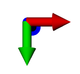
This section allows you to rotate a Layer.
You can rotate layers once or continuously.
| ▪ | X-Axis - Defines the clockwise or counter-clockwise rotation of the Layer in percent around the X-axis. |
| ▪ | Y-Axis - Defines the clockwise or counter-clockwise rotation of the Layer in percent around the Y-axis. |
| ▪ | Z-Axis - Defines the clockwise or counter-clockwise rotation of the Layer in percent around the Z-axis. |
| ▪ | Anti-Aliasing - Rotating a MADRIX Effect can produce hard edges for certain visuals. Anti-aliasing improves the image quality by reducing the hard edges. - Choose None, 2x, or 4x - [The higher the setting, the more performance will be required.] - The default value is None. |
![]() - Animates the Layer and rotates it around the corresponding axis permanently.
- Animates the Layer and rotates it around the corresponding axis permanently.
|
|
No Rotation |
X-Axis Rotation |
Y-Axis Rotation [Around the Y-axis] |
Z-Axis Rotation [Around the Z-axis] |
|
- |
- |
|
|
|
|
|
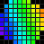
| ▪ | Set up a virtual LED matrix of 100 x 100 x 1. |
| ▪ | Use only 1 Layer. |
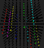
| ▪ | For Layer 1, choose SCE Graph and set Z-Axis to 45 in the section Rotation |
| ▪ | The result could look like this: |
This section allows you to duplicate the Layer and its content.
You can use it to create new repeating or mirrored patterns [Depending on the settings it might remind you of a kaleidoscope]. It also means that you can show the same content, and the same MADRIX Effects, on different parts of your LEDs or different LED fixtures.
| ▪ | Preset - Instead of adjusting the below values manually, you can decide to use these presets. MADRIX will then automatically adjust the below settings accordingly [except for Tile Count]. The default value is Full Size. |
| ▪ | Tile Count - Scales the Layer to a fraction of its size and therefore creates the number of tiles as set by this value. Is an automatic way to tile the Layer and influences the sizes below and always centers the positions. Tile mode Repeat is automatically activated. E.g., a Tile Count of 4 will reduce the size to 25% and create 4 Layers. |
| ▪ | Position X - Defines the horizontal position of the Layer. |
| ▪ | Position Y - Defines the vertical position of the Layer. |
| ▪ | Position Z - Defines the position of the Layer in the depth. |
| ▪ | Size X - Defines the horizontal size of the Layer. |
| ▪ | Size Y - Defines the vertical size of the Layer. |
| ▪ | Size Z - Defines the size of the Layer in the depth. |
| ▪ | Offset X - Defines the spacing between repeated or mirrored sections regarding the X-axis and only works when a Tile Mode other than None is selected. |
| ▪ | Offset Y - Defines the spacing between repeated or mirrored sections regarding the X-axis and only works when a Tile Mode other than None is selected. |
| ▪ | Offset Z - Defines the spacing between repeated or mirrored sections regarding the X-axis and only works when a Tile Mode other than None is selected. |
| ▪ | Tile Mode - You can choose to not apply tiling [None], to tile repeatedly [Repeat], horizontally [Mirror H], vertically [Mirror V], regarding the depth [Mirror D], or in any combination [e.g., Mirror HVD]. The default value is None. |
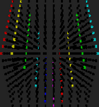
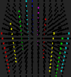
| ▪ | Set up a virtual LED matrix of 100 x 100 x 1. |
| ▪ | Use only 1 Layer. |
| ▪ | For Layer 1, choose SCE Wave / Radial and set Tile Count to 11 in the section Tiling |
| ▪ | The result could look like this: |
Using Fixture Groups As Tiling Preset
Fixture groups, when configured in the Patch Editor, are available as presets for Mapping and Tiling.
Learn more »Fixture Groups [Group Control]
1] Go to Tiling > Preset
- When your Patch includes Fixture Groups, as configured in the Patch Editor, the list of presets will include an item for each fixture group you have created. You will see the fixture group's Display Name.
- You will find these items below Full Size
2] Select the fixture group from the list.
3] MADRIX will automatically set the correct settings.
- The Tiling will be set according to the fixture group.
- The adjusted Map Settings will always be a rectangular selection. MADRIX uses the bounding box of the fixture group with its largest dimensions in X, Y, and Z.
| ▪ |
| ▪ |
Drag And Drop [Copy And Paste]
| ▪ | Left Mouse Click And Hold - You can perform a Copy and Paste with the mouse. Click with the left mouse button on the Map button and hold for 3 seconds. A small + appears. Now, continue to hold and drag the mouse to another Map button of another Layer and release the mouse to instantly copy the settings to the other Layer. |
| ▪ | Right Mouse Click - You can call up the context menu by performing a right mouse click on Map |
| ▪ | A small window will be shown. |
You can quickly perform the following actions:
| ▪ | Edit... - Opens the Map Settings window [in the same way you can open the window by clicking on Map with the left mouse button]. |
| ▪ | Open... - Loads Maps Settings from a previously saved, external file [of the file type *.mmapx]. A new window opens for you to select the file on your harddisk. |
| ▪ | Copy - Copies all your mapping, tiling, and rotation settings for this Layer into the clipboard. |
| ▪ | Paste - Applies all settings that are stored in the clipboard to this Layer. [In this way, you can quickly copy and paste Map Settings from one Layer to other Layers.] |
| ▪ | Clear - Clears all changes and restores the default settings [in the same way you can restore the default settings by clicking Defaults in the Map Settings window]. |