This topic includes:
▪Configuration Using A Web Browser
Configuration Using A Web Browser
When connected to Ethernet network, you can easily configure MADRIX ORION using the built-in web configuration interface.
You have 2 options to access the web interface. Both, ORION and your computer, need to be in the same network.
A] Using a standard web browser:
▪Connect MADRIX ORION and your computer to the same network.
▪Assign correct network settings for your PC in the Windows operating system.
[Recommended default settings: IP address 10.0.0.1 / Subnet mask 255.0.0.0]
[Please note: Your devices and the sender, such as the PC that runs MADRIX 5, need to have the same subnet mask!]
▪Open your web browser and enter the IP address of MADRIX ORION.
[You can find the default IP address on the back side of the device.]
▪The web configuration page will be launched. Now, you have access to various information and settings.
B] Using the MADRIX 5 Software:
▪Connect MADRIX ORION and your computer to the same network.
▪Assign correct network settings for your PC in the Windows operating system.
[Recommended default settings: IP address 10.0.0.1 / Subnet mask 255.0.0.0]
▪Go to the menu Tools > MADRIX Device Configuration...
[Keyboard shortcut: Ctrl+Alt+L]
▪Select your MADRIX ORION device in the list.
▪Click 
▪Your default web browser will open and the web configuration page will be launched. Now, you have access to various information and settings.
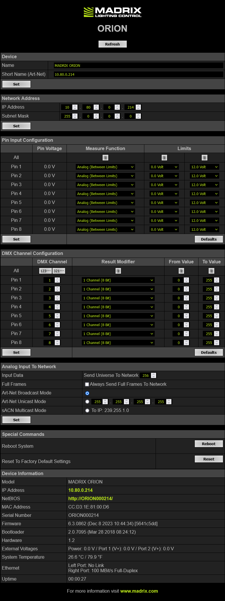
Device |
Name - Allows you to change the main label of the device by entering a name. The default setting is MADRIX ORION. ▪This refers to LongName within Art-Net with a maximum of 64 characters. ▪This refers to Source Name within sACN with a maximum of 63 characters. ▪This refers to the communication with the MADRIX 5 Software over Ethernet network or USB. Short Name (Art-Net) - Allows you to change the ShortName identifier used by Art-Net. The default setting is the IP address of the device. Confirm with Set |
Network Address |
You can change the basic network device settings. ▪IP Address ▪Subnet Mask |
Pin Input Configuration |
This section is an important part of the configuration. |
DMX Channel Configuration |
This section is an important part of the configuration. |
RDM |
ArtRdm (Act As RDM Responder) - Enables ArtRdm to be able to reply to RDM requests by an RDM controller as an RDM responder over Art-Net with status and sensor data. This enables monitoring of the device via MADRIX RADAR. The option is disabled by default. ▪Input Voltage [Power] ▪Port 1 Voltage ▪Port 2 Voltage ▪USB Power ▪Pin1 Voltage ▪Pin2 Voltage ▪Pin3 Voltage ▪Pin4 Voltage ▪Pin5 Voltage ▪Pin6 Voltage ▪Pin7 Voltage ▪Pin8 Voltage ▪Temperature ▪Device Model [incl. Hardware Revision] ▪Software Version [of the Firmware and Bootloader] ▪And device information, such as IP Address, Device Short/Long Name, etc. ▪Learn more Using RDM And MADRIX RADAR |
Analog Input To Network |
This section is an important part of the configuration. |
Special Commands |
Reboot - Reboot System - Restarts the device completely. [The website will automatically be reloaded after a few seconds.] Reset - Reset To Factory Default Settings - Restores the original settings of the device. [Since this may change back the IP address to the original setting, the website will automatically be reloaded after a few seconds and you will automatically be redirected to the correct website and IP address.] |
Device Information |
This section displays various details about the device, including: ▪Model ▪IP Address ▪NetBIOS ▪MAC Address ▪Serial Number ▪Firmware ▪Bootloader ▪Hardware ▪External Voltages ▪System Temperature ▪Ethernet ▪Up Time |
This section is an important part of the configuration. It allows you to specify how the input data is parameterized.
▪You can change the settings for each of the 8 input pins individually [Pin 1 - Pin 8].
▪Pin Voltage - Shows how much volt is applied at the particular pin.
▪Measure Function - Defines how the input data is parameterized. Confirm with Set or restore the default values with Defaults. Choose from different options:
▪![]() Sets the value of the first port for all ports for the relevant column.
Sets the value of the first port for all ports for the relevant column.
Disabled |
▪Deactivates the specified pin. ▪This also frees up DMX channels as well as processing resources. ▪The more pins are deactivated, the higher the measure frequency can be [12.5 FPS / Hz for 8 pins and up to 100 FPS / Hz for 1 pin]. |
Analog |
▪Linearly measures the incoming voltage at the particular pin. ▪In addition, you can specify the lower and upper limit in which the device measures the analog signal by setting them with help of the Current Limit Values |
Digital |
▪Measures the incoming voltage at the particular pin, but interprets it digitally. ▪The lower and upper limit, which are set by Limits, are used as thresholds. ▪Once the signal goes below or above those limits, the provided result changes to the low or to the high value accordingly. ▪Low value and high value are directly set via From Value and To Value in the DMX Channel Configuration |
Pin Voltage |
▪Measures the incoming voltage at the particular pin. ▪In addition, you can specify the lower and upper limit in which the device measures the analog signal by setting them with help of the Limits ▪The result will be provided as decimal value. ▪If you are using 8 bit with 1 DMX channel as Result Modifier in the DMX Channel Configuration, the main value before the comma will be provided as result (e.g. 3 Volt). ▪If you are using 16 bit with 2 DMX channels as Result Modifier in the DMX Channel Configuration, both values, before and after the comma, will be provided as result (e.g. 3.12 Volt). |
External Voltage |
▪Measures the incoming voltage at Power. ▪In addition, you can specify the lower and upper limit in which the device measures the analog signal by setting them with help of the Limits ▪The result will be provided as decimal value. ▪If you are using 8 bit with 1 DMX channel as Result Modifier in the DMX Channel Configuration, the main value before the comma will be provided as result (e.g. 3 Volt). ▪If you are using 16 bit with 2 DMX channels as Result Modifier in the DMX Channel Configuration, both values, before and after the comma, will be provided as result (e.g. 3.12 Volt). |
Counter |
▪Measures the incoming voltage at the particular pin, but interprets it digitally. ▪The lower and upper limit, which are set by Limits, are used as thresholds. ▪Once the signal goes below or above those limits, the provided result is increased by 1. ▪Low value and high value are directly set via From Value and To Value in the DMX Channel Configuration |
Count Per Second |
▪Measures the incoming voltage at the particular pin, but interprets it digitally. ▪The lower and upper limit, which are set by Limits, are used as thresholds. ▪Once the signal goes below or above those limits, it is counted towards the provided result per second. ▪Low value and high value are directly set via From Value and To Value in the DMX Channel Configuration ▪Due to the processing, only signals that result in a maximum of 100 counts and are thus slower than 50 FPS (< 50 Hz) can be measured. |
Count Per Second |
▪Measures the incoming voltage at the particular pin, but interprets it digitally. ▪The lower and upper limit, which are set by Limits, are used as thresholds. ▪Once the signal goes below or above those limits, it is counted towards the provided result per second. ▪Low value and high value are directly set via From Value and To Value in the DMX Channel Configuration ▪The device exclusively monitors this particular pin for a quarter of a second. Thus, very high counts can be possible. The count will then be multiplied by 4 and provided as result in FPS /Hz. |
Beats Per Minute |
▪Measures the incoming voltage at the particular pin, but interprets it digitally. ▪The lower and upper limit, which are set by Limits, are used as thresholds. ▪Once the signal goes below or above those limits, it is counted towards the provided result per second. ▪Low value and high value are directly set via From Value and To Value in the DMX Channel Configuration ▪The the device monitors the time between low and high threshold counts and recalculates them to FPS / Hz. |
Signal Slope Detections |
▪Measures the incoming voltage at the particular pin, but interprets it digitally. ▪The lower and upper limit, which are set by Limits, are used as thresholds. ▪Once the signal goes below or above those limits, it is counted towards the provided result per second. ▪Low value and high value are directly set via From Value and To Value in the DMX Channel Configuration ▪The device monitors each low and high threshold count and sets the provided result for 1 second to the To Value. Afterwards, the provided result will be set to the From Value again. ▪Due to the processing, it makes it possible to reliably detect very short impulses. |
Time Interval (Short) |
▪Measures the incoming voltage at the particular pin, but interprets it digitally. ▪A 16-bit counter continuously counts up the milliseconds [ms]. ▪The current value [time interval] is always being sent out on 2 DMX channels [0 to 255 coarse, 0 to 255 fine]. Fine is counted up first. ▪The lower and upper limit, which are set by Limits, are used as thresholds. ▪When triggered via the input pin and once the signal goes below the minimum limit, it is being registered as a positive signal [flank]. That is why the minimum limit should be > 0 V. ▪If a positive signal [flank] is being registered, the counter is reset to 0. ▪If no flank is being registered, the counter counts to a maximum of 65536 [255, 255]. ▪Time Interval (Short) counts 1/100s of a second and ends at 10.9 minutes. ▪When setting the Result Modifier to 8-bit instead of 16-bit, a maximum of 2.55 seconds is being counted. |
Time Interval (Long) |
▪Measures the incoming voltage at the particular pin, but interprets it digitally. ▪A 16-bit counter continuously counts up the seconds [s]. ▪The current value [time interval] is always being sent out on 2 DMX channels [0 to 255 coarse, 0 to 255 fine]. Fine is counted up first. ▪The lower and upper limit, which are set by Limits, are used as thresholds. ▪When triggered via the input pin and once the signal goes below the minimum limit, it is being registered as a positive signal [flank]. That is why the minimum limit should be > 0 V. ▪If a positive signal [flank] is being registered, the counter is reset to 0. ▪If no flank is being registered, the counter counts to a maximum of 65536 [255, 255]. ▪Time Interval (Long) counts the seconds and ends at 18.2 hours. ▪When setting the Result Modifier to 8-bit instead of 16-bit, a maximum of 255 seconds is being counted. |
▪Limits - Defines in which range the analog input signal is received. Confirm with Set or restore the default values with Defaults. Choose from different options for the minimum value and maximum value:
- 0.0 Volt
- 1.0 Volt
- 2.0 Volt
- 3.0 Volt
- 4.0 Volt
- 5.0 Volt
- 6.0 Volt
- 7.0 Volt
- 8.0 Volt
- 9.0 Volt
- 10.0 Volt
- 11.0 Volt
- 12.0 Volt
- 10 % Of V+
- 25 % Of V+
- 50 % Of V+
- 75 % Of V+
- 90 % Of V+
- 100 % Of V+
This section is an important part of the configuration. It allows you to specify how the input data is sent out.
▪You can change the settings for each of the 8 input pins individually [Pin 1 - Pin 8].
▪![]() Sets the value of the first port for all ports for the relevant column.
Sets the value of the first port for all ports for the relevant column.
▪![]() Automatically and consecutively numbers all DMX channels in ascending or descending order based on the first pin.
Automatically and consecutively numbers all DMX channels in ascending or descending order based on the first pin.
▪DMX Channel - Defines on which channel the data is sent.
- For 8 Bit - This defines the channel for each individual pin.
- For 16 Bit - This defines the start channel. 2 channels are required per pin. Make sure to correctly set up all other channels without overlapping channel assignments!
▪Result Modifier - Defines how the data is processed.
- 1 Channel (8 Bit)
- 1 Channel (8 Bit), Inverted
- 2 Channels (16 Bit) [First Channel: Coarse, Second Channel: Fine]
- 2 Channels (16 Bit), Inverted [First Channel: Coarse Inverted, Second Channel: Fine Inverted]
- 2 Channels (16 Bit), Swapped [First Channel: Fine, Second Channel: Coarse]
- 2 Channels (16 Bit), Inverted, Swapped [First Channel: Fine Inverted, Second Channel: Coarse Inverted]
▪From Value - Defines the DMX value range. This is the minimum value.
▪To Value - Defines the DMX value range. This is the maximum value.
This section is an important part of the configuration. It allows you to specify the network settings.
When data is received through the ports, MADRIX ORION will automatically forward it to Ethernet network.
▪Input Data > Send Universe To Network - ORION receives input data worth up to 16 DMX channels. This setting specifies on which universe the data is sent into the network [Art-Net universe or Streaming ACN universe.]
- By default, 256 is selected. Valid values range from 1 to 256.
▪Full Frames > Always Send Full Frames To Network - If activated, ORION will always send out 512 channels on the specified network universe.
- ORION automatically sends values of 0 on channels that are not used.
▪Art-Net Broadcast Mode - Activates Art-Net and broadcasts the data into the network.
▪Art-Net Unicast Mode - Activates Art-Net and only sends data to the specified IP address in order to reduce network traffic and bandwidth.
- Make sure to set up the correct IP address where to send the data to.
▪sACN Multicast Mode - Activates Streaming ACN. This mode multicasts data to the fixed IP address 293.255.1.0 according to the sACN specifications.
| MADRIX 6.06. |
| [Ctrl & +/-] = Zoom In/Out | [Ctrl & 0] = 100% |
|
Previous Next
|
|
Enable Automatic Translation | Activer La Traduction Automatique | 启用自动翻译 |