Overview
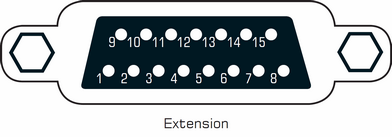
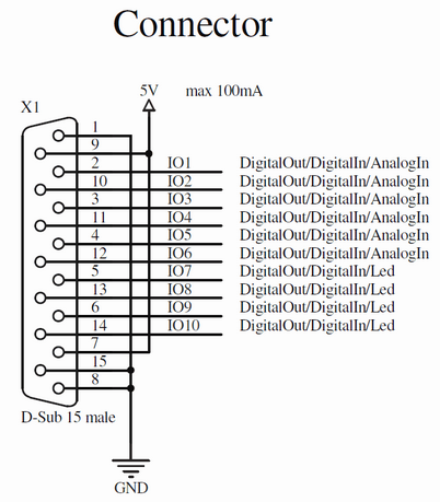
MADRIX PLEXUS features a 15-pin, serial connector with individually addressable ports. The extension port makes it possible to connect external analog or digital devices for remote control.
Extension port specifications: 15-pin, D-Sub, US, female
In MADRIX, please open the menu 'Tools' > 'PLEXUS Configuration…' > 'Extension Ports' to configure each port individually for the corresponding PLEXUSConfiguration. Select a PLEXUS Configuration first. For more information, see Stand-Alone Mode.
Available Settings
The following table shows available settings of the individual pins:
Pin |
Assignment |
Available Settings |
1 |
Ground |
|
2 |
Port 1 |
Digital Input, Digital Output, Analog Input |
3 |
Port 3 |
Digital Input, Digital Output, Analog Input |
4 |
Port 5 |
Digital Input, Digital Output, Analog Input |
5 |
Port 7 |
Digital Input, Digital Output |
6 |
Port 9 |
Digital Input, Digital Output |
7 |
Power |
5V, 100 mA max. (shared with Pin 9) |
8 |
Ground |
|
9 |
Power |
5V, 100 mA max. (shared with Pin 7) |
10 |
Port 2 |
Digital Input, Digital Output, Analog Input |
11 |
Port 4 |
Digital Input, Digital Output, Analog Input |
12 |
Port 6 |
Digital Input, Digital Output, Analog Input |
13 |
Port 8 |
Digital Input, Digital Output |
14 |
Port 10 |
Digital Input, Digital Output |
15 |
Ground |
|
Note: A maximum of 100 mA can be shared across pins. The combined power of Pin 7 and Pin 9 can be a maximum of 100 mA.
General Functionality
You can connect different equipment to these Ports. In general, the Port can work as an input to receive a signal from external equipment. According to your PLEXUS Configuration, it can then trigger a certain action/behavior. Or it can function as output to send a signal to the external equipment, which then can process this signal.
Examples Of Equipment You Can Connect
You may attached external analog or digital devices to the extension port.
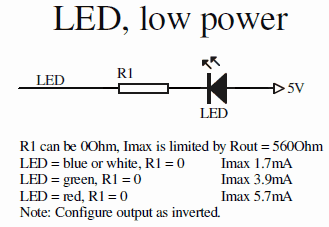
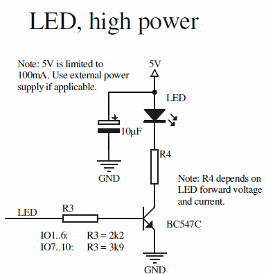
Examples include for example external buttons, light barriers, small light diodes.
Technical Information
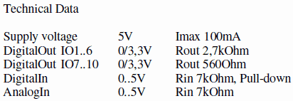
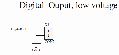
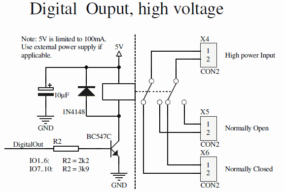
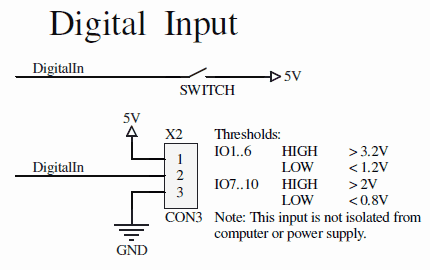
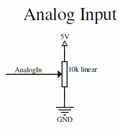
The following drawings provide further, technical details on how to use the extension port.
Using An External 15-pin Connector
|
General Technical Data
|
Using A Port As Digital Output
|
Using A Port As Digital Input
|
Using Light Diodes
|
Using A Port As Analog Input
|
