This topic includes:
| ▪ | Menu |
You need to tell MADRIX
1] which LED fixtures you are going to use.
2] how many LED fixtures you are going to use.
3] how they are placed.
This configuration of the virtual LED matrix is stored in a so-called Patch file.
Setting up the virtual LED matrix/the Patch file is a requirement! It is necessary for the initial configuration of MADRIX.
MADRIX offers 2 tools for this task:
| ▪ | Matrix Generator |
| ▪ | Patch Editor |
The Matrix Generator helps you to generate a virtual LED matrix automatically according to your settings. This automatic process can be very helpful, when your LED installation is set up in a very simple, logical, or linear way and only uses 1 fixture type. The Patch file will be automatically generated by MADRIX for you.
The Patch Editor is a graphical editor to directly create the Patch file. The Patch Editor offers the same functions as the Matrix Generator and many more options. It allows you to configure your virtual matrix in great detail. You can place LED fixtures freely and individually. If you have more than 1 kind of fixture, use the Patch Editor.
This topic explains the Patch Editor.
Note: If you want to use DVI fixtures, please read this chapter and the chapter »DVI Patch
[The chapters Patch Editor and DVI Patch are about one and the same tool. The term DVI Patch specifically refers to working with DVI fixtures.]
To work with the Patch Editor, follow these steps:
1] Open the Patch Editor.
2] Delete all currently included fixtures [except when they are needed].
3] Add and configure all fixtures you require.
4] Set up the Matrix Size.
5] Close the Patch Editor.
1] Open The Patch
| ▪ | Go to Preferences > Patch Editor... [Keyboard shortcut: F3] |
| ▪ | A new window will open. |
| ▪ | The Patch Editor is a separate window. Hence, you will be able to control MADRIX while working with the Patch Editor. |
2] Delete Fixtures
| ▪ | Click Select All to select all fixtures or single-handedly select unnecessary fixtures. [Keyboard shortcut: Ctrl+A] |
| ▪ | Click Delete - to delete the selected fixtures from the workspace. [Keyboard shortcut: Del] |
| ▪ | You can also click New to create a new Patch file and remove all fixtures at once. [Menu File > New Patch; Keyboard shortcut: Ctrl+N] |
3] Add And Configure Fixtures
| ▪ | Click Add + to add new fixtures to the workspace. [Keyboard shortcut: Ins] |
| ▪ | A new window will open. |
| ▪ | Add your fixtures as explained in the chapter »Matrix Generator and consider the following settings additionally: - The Start Fixture ID needs to be a number that is not yet occupied by fixtures in the Patch. Each fixture needs its own, unique Fixture ID. MADRIX will automatically provide the next number that is free to use. [You will not be able to add new fixtures if an ID is not unique.] - You can choose not to set up all Addressing in the Add Fixtures window. The Patch Editor allows you to configure each fixture individually later. - But make sure to set up Start Position X / Y / Z. This will position fixtures correctly on the workspace and prevent fixtures to overlap. [You will not be able to add new fixtures if their positions overlap. However, you can intentionally allow overlapping fixtures if you want to as explained below.] - Click Add to add your fixtures. |
| ▪ | Configure your fixtures further if needed. [Please see below] |
| ▪ | Repeat the steps to add more fixtures or fixtures of different types. |
| ▪ | The Patch Editor is very flexible. Fixtures can simply and are often required to be rearranged, readdressed, added, and deleted later. Adding fixtures is an initial step to create the individual Patch for your individual LED installation. |
| ▪ | Click Close to close the window. |

| ▪ | After you have set up and configured all of your fixtures, it is important to define the Matrix Size. |
| ▪ | Click Matrix Size [menu Edit > Matrix Size...] |
| ▪ | A new window will open. |
The virtual LED matrix represents your LED fixtures. Therefore, it is the area on which the MADRIX Effects are rendered and displayed, and ultimately sent to your output. MADRIX needs to know in pixels/voxels how large your LED project is in total.
Set up the Matrix Size according to all of these parameters:
| ▪ | Size X - Defines the total size of the virtual LED matrix in X in pixels/voxels [horizontal; width]. |
| ▪ | Size Y - Defines the total size of the virtual LED matrix in Y in pixels/voxels [vertical; height]. |
| ▪ | Size Z - Defines the total size of the virtual LED matrix in Z in pixels/voxels [level; depth]. - Choose Size Z = 1 to work in 2D. - Choose a value higher than 1 and MADRIX will automatically create a virtual matrix in 3D. |
| ▪ | Color Depth - Defines the number of color channels your LED fixtures use. [For example, a color depth of 3 resembles RGB and a color depth of 4 represents RGBW.] |
| ▪ | Confirm your changes with OK |
5] Close The Patch Editor
| ▪ | Close the Patch Editor when you have fully set up and configured your Patch correctly. [Continue to learn how to work with the Patch Editor below.] |
| ▪ | When you want to close the Patch Editor, click X or go to the menu File > Close when you want to close the Patch Editor. [Keyboard shortcut: F3] |
| ▪ | When you save your MADRIX Setup file, the Patch file is automatically included. |
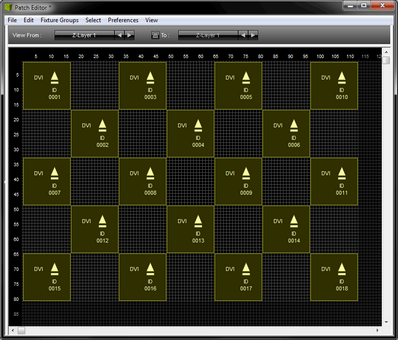
| ▪ | Note: Each LED project is different. That is why each Patch in the Patch Editor will look different. There are no general settings that can be applied to every project. Instead, please make sure that the Patch is set up in MADRIX according to your individual LED installation. |
| ▪ | Here are just a few examples of how a Patch could look like: |
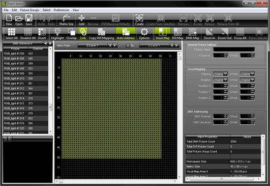
User Interface Of The Patch Editor
Overview
The user interface of the Patch Editor is divided into several, different parts.
| ▪ | On top, you will find the menu. |
| ▪ | Below the menu, you see the toolbar. |
| ▪ | Below the toolbar, 3 sections are available. |
| ▪ | On the left side, you see the Fixture List. |
| ▪ | The middle section represents a graphical version of your workspace and of your virtual LED matrix. [There are three different view modes available for this section. Learn more below.] |
| ▪ | On the right side, you can use various settings for the fixture configuration. |
| ▪ | Rearrange the width of each section by dragging the section edges. |
| ▪ | Hide the left section or the right section by dragging their edge to the outer border of the Patch Editor window. Display them again by dragging the border back. |
Choose View > Restore Default Window Layout in order to reset the layout of the Patch Editor to its original settings [or if you are experiencing graphical glitches].
Menu And Toolbar
The Patch Editor has a separate menu and a toolbar for shortcuts:
| ▪ | All items of the menu are explained below. |
| ▪ | The toolbar provides shortcuts to convenient tasks and includes the majority of options that are also included in the menu. - You can rearrange the toolbar using Left Mouse Click And Drag And Drop |

Fixture List [Left Side]
The left side of the Patch Editor shows the Fixture List:
| ▪ | The Fixture List provides information and allows you to select specific fixtures. - You can choose to show DVI fixtures [DVI] and DMX fixtures [DMX Universes]. Select it if you want to see DVI fixtures or which particular DMX universe. - DMX fixtures are shown with their name, index number, and DMX start channel. - DVI fixtures are shown with their index number, and if DVI Mapping is active. - Select fixtures with your mouse and they will be automatically selected in the graphical middle section. Select several fixtures by using the Shift or Ctrl button in addition. - Select the Fixture List and use the Left Arrow Key and the Right Arrow Key to navigate through all DMX Universes and DVI. |
Fixture Configuration [Right Side]
The right side of the Patch Editor is a context-sensitive panel that shows different items depending on your selection [fixtures, fixture groups, no selection].
| ▪ | Learn more about the right section to configure your fixtures below. |

Graphical Overview [Middle Section]
| ▪ | The middle section is the most important section. |
| ▪ | 3 view modes are available for the graphical overview: - Voxel Map - Is the default view mode to work with the Patch Editor. The following explanations mainly reference this view mode! - DVI Map - Is only relevant when working with DVI fixtures. Learn more »DVI Patch - DMX Map - Allows you to view the Patch with regards to occupied and used DMX channels. This mode will be explained separately. Learn more DMX Map |
| ▪ | The Voxel Map shows fixtures and settings in the following ways: - The size of the virtual LED matrix [Matrix Size] is shown with the help of a light gray grid. - The total workspace you can work on is shown with the help of a dark gray grid. - You can see the position of fixtures. - DVI fixtures are displayed in dark yellow. - Selected DVI fixtures are displayed in yellow. - DMX fixtures are displayed in dark green. - Selected DMX fixtures are displayed in green. - There is an integrated system for error and information messages. A message box will be displayed at the bottom of the middle section. Close the message with x |


![]()
The following work-flows are mainly relevant for the view mode Voxel Map, but can also work selectively in the DMX Map.
| ▪ | Ctrl+N - This is a keyboard shortcut that will perform the action directly rather than using the menu. |
| ▪ | ... - Indicates that an extra window will open on top of the Patch Editor window. |
File Menu

| ▪ | New Patch - Removes all fixtures and creates a new and empty workspace [MADRIX can only have one Patch file at a time]. |
| ▪ | Open Patch... - Loads a previously saved patch file. |
| ▪ | Save Patch - Saves the Patch file in its current state. |
| ▪ | Save Patch As... - Saves the Patch file as a new file; a copy. |
| ▪ | Update Fixtures From Library - Allows you to refresh all fixture profiles in the Patch from the currently loaded MADRIX Fixture Library, in case you changed fixture profiles that are included in the Fixture Library with the help of the Fixture Editor. Changing the fixture profiles after creating the Patch can sometimes be necessary and is often easier than creating the Patch again from the beginning [MADRIX will not update fixtures under certain cirumstances. That is the case, when the Fixture Library does not contain the fixture type, i.e. the unique fixture ID is not included (UUID), or when a DVI fixture is made out of more voxels than defined in the Fixture Library, for example when having chosen Merge Fixtures while adding them.] |
| ▪ | Export Selected Fixture... - Allows you to save a fixture directly from the Patch to an external file [of the file type *.mfxx] without using the Fixture Editor. Simply select a fixture in the Patch Editor first. Then, choose a name. |
| ▪ | Close - Closes the Patch Editor. |
Edit Menu

| ▪ | Undo - Restores the previous state of the Patch and reverts your last actions. |
| ▪ | Redo - Recreates the state again after having performed an Undo. |
| ▪ | Matrix Size... - Defines the main settings of the Patch file [as explained above]. |
| ▪ | Add Fixtures... - Opens a new window in order to add fixtures to the workspace. |
| ▪ | Remove Selected Fixtures - Removes the selected fixtures from the workspace. |
| ▪ | Restore DVI Mapping Defaults For Selection - Is only relevant when working with DVI fixtures. Learn more »DVI Patch |
| ▪ | Rotate Selection By 90° - Changes the rotation of the selected fixtures by 90°. |
| ▪ | Rotate Selection By 180° - Changes the rotation of the selected fixtures by 180°. |
| ▪ | Rotate Selection By 270° - Changes the rotation of the selected fixtures by 270°. - When rotating multiple fixtures, these 3 functions will rotate the entire block of fixtures. The position of each fixture will change as they are rotated using the central point of all fixtures. - Therefore, it is different to the Rotation that can be applied in the section Fixture Settings. That function will rotate each fixture individually and not change the positions. |
Fixture Groups Menu

| ▪ | Create Emptry Fixture Group - Creates a fixture groups which does not contain any fixtures yet. |
| ▪ | Create Fixture Group From Selected Fixtures - Creates a fixture group that automatically includes all fixtures that have been selected before. |
| ▪ | Remove Selected Fixture Groups - Removes all fixture groups that are currently selected from the Patch. |
| ▪ | Assign Selected Fixtures To Selected Fixtures Groups - Adds all currently selected fixtures to all fixture groups that are currently selected. |
| ▪ | Release Selected Fixtures From Selected Fixture Groups - Releases all currently selected fixtures from all fixture groups that are currently selected. |
| ▪ | Release Selected Fixtures From All Fixture Groups - Releases all currently selected fixtures from all fixture groups that they are assigned to. |
| ▪ | Learn more »Fixture Groups [Group Control] |
Select Menu

| ▪ | Select All - Selects every single fixture that is included in your Patch. At the same time, all fixtures will be selected in the Fixture list on the left. |
| ▪ | Deselect All - Unselects all currently selected fixtures. |
| ▪ | Invert Selection - Selects every fixture except the ones you have currently selected. |
Preferences Menu

| ▪ | Highlight Selected Fixtures - Makes selected fixtures flash with white color. This makes it easier to identify and see them on stage. This feature is available for DMX-based fixtures. |
| ▪ | Allow Fixtures To Overlap - Allows fixtures as well as their DVI Mapping to be arranged on top of each other on the virtual LED matrix. If deactivated, you cannot place any fixture on a position that is already occupied by another fixture. |
| ▪ | Link DVI Mapping And Voxel Mapping - Is only relevant when working with DVI fixtures. Learn more »DVI Patch |
| ▪ | Copy DVI Mapping - Is only relevant when working with DVI fixtures. Learn more »DVI Patch |
| ▪ | Automatically Address Copied DMX Fixtures - Enables that MADRIX automatically sets up the DMX addresses for DMX fixtures that are copied. Learn more below. |
| ▪ | Options... - Will open a new window in order to change various options of the Patch. |
View Menu

| ▪ | Voxel Map - Is one of three view modes. It is the default view mode to work with the Patch Editor. |
| ▪ | DVI Map - Is one of three view modes. It is only relevant when working with DVI fixtures. Learn more »DVI Patch |
| ▪ | DMX Map - Is one of three view modes. Allows you to view the Patch with regards to occupied and used DMX channels. Learn more DMX Map |
| ▪ | Zoom In - Determines the level of detail. Zoom in to see single fixtures, their assigned universe, channel, and rotation. |
| ▪ | Zoom Out - Determines the level of detail and allows you to see more of the workspace. |
| ▪ | Focus All - Automatically adjusts the zoom level to show all fixtures on the workspace. |
| ▪ | Focus Selection - Automatically adjusts the zoom level to show all currently selected fixtures. |
| ▪ | File Toolbar - Shows or hides the corresponding toolbar and icons. |
| ▪ | Edit Toolbar - Shows or hides the corresponding toolbar and icons. |
| ▪ | Fixture Groups Toolbar - Shows or hides the corresponding toolbar and icons. |
| ▪ | Select Toolbar - Shows or hides the corresponding toolbar and icons. |
| ▪ | Preferences Toolbar - Shows or hides the corresponding toolbar and icons. |
| ▪ | View Toolbar - Shows or hides the corresponding toolbar and icons. |
| ▪ | Restore Default Window Layout - Restores the default user interface and layout of the Patch Editor. |
Overview
| ▪ | In the Patch Editor, go to Preferences > Options... [Keyboard shortcut: Ctrl+Alt+O] |
| ▪ | In the options, you can change the size of the workspace and the history size for undo and redo. |
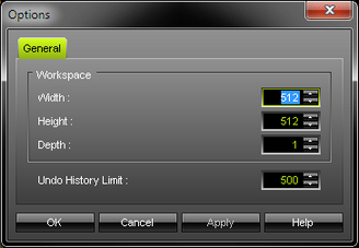
Workspace
The workspace allows you to freely position fixtures and work with them on a grid.
By default, the workspace size is set to 512 x 512 x 1 pixels [X x Y x Z].
| ▪ | If needed, change the size of the workspace according to your needs by adjusting Width, Height, and Depth |
| ▪ | MADRIX will automatically increase the size of the workspace if you are adding fixtures to positions that are outside of the current workspace size. |
Note: The workspace is the large grid you are working on. In contrast, the virtual LED matrix [i.e., Matrix Size] tells MADRIX the total size of the fixtures and the LED installation.
Undo And Redo
You can use Undo and Redo to revert actions while working in the Patch Editor.
By default, the Patch Editor allows 500 steps to be reversed.
| ▪ | If needed, change this so-called Undo History Limit according to your needs. |
The Patch Editor can provide a useful overview over the most important settings, such as Matrix Size and Workspace. The overview is provided in the lower right corner. First, make sure that no fixture is selected!
| ▪ | Patch Properties - The following information is available to you: - Total DMX Fixture Count - Shows the overall number of DMX fixtures that are currently included in your Patch file. - Total DVI Fixture Count - Shows the overall number of DVI fixtures that are currently included in your Patch file. - Total Fixture Group Count - Shows the overall number of Fixture Groups that are currently included in your Patch file. - Workspace Size - Shows the currently set up size of the Workspace - Matrix Size - Shows the currently set up Matrix Size - Voxel Map Area X - Shows the size of the area on which fixtures are patched and located in X, independently of the Matrix Size that is defined. - Voxel Map Area X - Shows the size of the area on which fixtures are patched and located in Y, independently of the Matrix Size that is defined. - Voxel Map Area X - Shows the size of the area on which fixtures are patched and located in Z, independently of the Matrix Size that is defined. - DVI Map Area X - Is only visible when DVI fixtures are included in the Patch. Shows the size of the area on which DVI fixtures with DVI Mapping are patched and located in X. »DVI Patch - DVI Map Area Y - Is only visible when DVI fixtures are included in the Patch. Shows the size of the area on which DVI fixtures with DVI Mapping are patched and located in Y. »DVI Patch - DVI Map Area Z - Is only visible when DVI fixtures are included in the Patch. Shows the size of the area on which DVI fixtures with DVI Mapping are patched and located in Z. »DVI Patch |
Overview
| ▪ | MADRIX can control 2D projects as well as 3D projects. Learn more »2D Or 3D [X, Y, Z] |
| ▪ | You automatically choose to work in 2D or in 3D, when you add new fixtures or set up the virtual LED matrix [Matrix Size]. Learn more above |
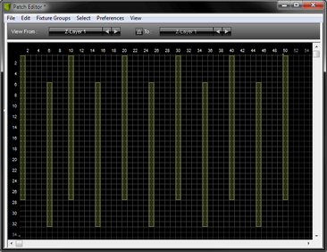
Z-Levels
Make sure to select the view mode Voxel Map first.
| ▪ | The Patch Editor only provides a 2D, graphical representation, even if you are working in 3D. |
| ▪ | To access and configure all fixtures of a 3D project, you can select the different Z-levels that make up your project. |
| ▪ | When working in 2D, only one Z-level is needed and available [Z-Layer 1]. |
![]()
| ▪ | When working in 3D, you can select and view each Z-level according to your needs. A] You want to select only one Z-level: 1] View From - Select the Z-Layer you wish to see and work with. 2] Leave To deactivated. 3] You will be able to select and work with the fixtures of only 1 Z-level at a time. B] You want to select several [if not all] Z-levels at once: 1] View From - Select the first Z-Layer you wish to see and work with. 2] To - Activate it. Then, select the last Z-Layer you wish to work with. 3] All Z-levels and their corresponding fixtures within that range of Z-levels will be selectable. Example: If you want to select and work with all fixtures of your 3D project that features 10 Z-levels, set up View From Z-Layer 1 To Z-Layer 10  - If you now want to select all fixtures, click Select All [or press Ctrl+A]. - If you want to select one fixture, simply click on it. - If you want to select a fixture and all other corresponding fixtures on the same position on each Z-level, make sure to use the ways of selecting multiple fixtures as described below [e.g., rectangular selection mode via Shift]. - If you are selecting multiple fixtures on the Z-level you currently see, all corresponding fixtures on each Z-level will also be selected. - Use the Fixture List [on the left side of the Patch Editor] to double-check which fixtures you have currently selected. |
| ▪ | More Information: |
|
|
The following work-flows are mainly relevant for the view mode Voxel Map, but can also work selectively in the DMX Map.
Overview
| ▪ | Selection A] Left click on a single fixture in the graphical middle section in order to select it. B] Left click a fixture in the Fixture List and it will automatically be selected in the graphical middle section. |
| ▪ | Multiple Selection A] Left click on fixtures while holding Ctrl on your keyboard in order to select several fixtures. B] Hold Shift on your keyboard. Then, hold your left mouse button and drag your mouse. A selection mask will become visible. It is displayed with the help of a dotted line. Additionally, hold the Ctrl button and you will be able to select different areas of the Patch which will be added to your selection. C] Hold Shift, left-click the first fixture, then left-click the last fixture, and applying a rectangular selection mode, every single fixture between the first and the last fixture will be selected. Hold Ctrl and Shift at the same time and you can select different fixtures each time, while the previously selected fixtures remain selected. D] Select several fixtures via Shift+Left click or Ctrl+left click in the Fixture List and they will be automatically selected in the graphical middle section. |
| ▪ | Zoom - Use the scroll wheel to zoom in or to zoom out. |
| ▪ | Navigation - Press Space and left click in order to drag the graphical middle section for navigation. [You can also use the scroll bars.] |
| ▪ | Position [Drag And Drop] - Select a fixture and hold the mouse button. Then, move your cursor. Your selection will stand out from the rest of the Patch. Drop it on the new position and it will automatically snap to this position according to the grid. - This also works with multiple fixtures. - Use drag and drop in combination with Ctrl to copy fixtures and the DMX universe and DMX channel will be automatically adjusted [if this option is activated in the menu]. Learn more Copying Fixtures |
| ▪ | Position [Keyboard] - Select one or several fixtures and use the arrow keys on your keyboard to move them to a different position. |
| ▪ | Rotation - Select multiple fixtures and use Page Up or Page Down on your keyboard to rotate the entire block of fixtures. They will be literally rotated using the central point of all fixtures. Hence, the position will be changed automatically. [In contrast, if you select several fixtures and adjust the Rotation in the Fixture settings, each fixture will be rotated individually. Their positions will not change. ] |
Copying DVI Fixtures
Single DVI Fixtures
| ▪ | Select a single DVI fixture while holding Ctrl. Then, continue to hold Ctrl and the left mouse button and drag your mouse and a copy of the DVI fixture will be created. Simply release the mouse at the fixture's new position. |
Multiple DVI Fixtures
| ▪ | Select multiple DVI fixtures while holding Ctrl. Now hold down the left mouse button at the same time on any of the selected fixtures. Drag your mouse and copies of the DVI fixtures in a corresponding pattern will be created. Simply release the mouse at the fixtures' new position. |
Copying DMX Fixtures [Auto Addressing]
Overview
Pay attention when using auto addressing and double-check if each fixture is addressed correctly!
| ▪ | Copying DMX fixtures has been improved by adding auto addressing. |
| ▪ | If auto addressing is enabled, MADRIX will automatically increase the DMX channel [and DMX universe] of the copied fixture. |
| ▪ | In the Patch Editor, go to Preferences > Automatically Address Copied DMX Fixtures to activate auto addressing. |
| ▪ | Disable this feature and the copied fixtures will have the same DMX channel and universe as their sources. |
Single Fixtures
| ▪ | Select a single DMX fixture while holding Ctrl. Then, continue to hold Ctrl and the left mouse button and drag your mouse and a copy of the DVI fixture will be created. Simply release the mouse at the fixture's new position. |
| ▪ | The DMX channel and the DMX universe will be automatically adjusted if auto addressing is enabled. |
| ▪ | Example: The original fixture at position 1,1 is patched to DMX universe 1 and channel 1. It requires 3 DMX channels. Therefore the first copy, fixture number 2, is automatically set to channel 4, and so on. |

Multiple Fixtures
| ▪ | If you select several DMX fixtures, auto addressing also works. The intelligent function calculates the next free DMX address for each of the copied DMX fixtures and automatically adjusts the DMX channel and the DMX universe for each fixture. |
| ▪ | Example 1: A row of four linearly addressed fixtures shall be copied at once [6 DMX channels per fixture]. Result: Each fixture will be addressed to the next free DMX address in comparison to the previous fixture. |
| ▪ | Example 2: A row of four linearly addressed fixtures shall be copied at once, while fixture number 3 has a higher address than fixture number 4 [6 DMX channels per fixture]. Result: Fixture number 7 has also a higher DMX address than fixture number 8. |
| ▪ | Example 3: A row of three linearly addressed fixtures should be copied at once, while spacing and an offset is added to fixture number 3 [6 DMX channels per fixture]. Result: Fixture number 6 continues with the next free addressing of fixture number 5 and does not have an additional offset, while keeping the spacing. |
Highlight Selected Fixtures
|
|

Allow Fixtures To Overlap
|
|

The following work-flows are mainly relevant for the view mode Voxel Map, but can also work selectively in the DMX Map.
Overview
| ▪ | In order to configure a fixture in the Patch Editor, select it first. |
| ▪ | The corresponding information will be displayed in the third column. |
| ▪ | When selecting multiple fixtures, settings can be confirmed with OK and will apply to each fixture individually. |
| ▪ | Configure each fixture according to your requirements! |

| ▪ | General Fixture Settings - Display Name - Defines a label for the fixture. - Fixture ID - Defines the unique identifier for this fixture. Each fixture needs its own, unique Fixture ID. - Always confirm with OK |
| ▪ | Voxel Mapping - Includes settings that refer especially to pixel mapping and voxel mapping [e.g., the position of fixtures]. - Flipping - Allows you to flip a fixture horizontally, vertically, or both. Learn more below - Rotation - Allows you to rotate a fixture. Learn more below - Position X - Defines the horizontal position of the fixture. - Position Y - Defines the vertical position of the fixture. - Position Z - Defines the depth position of the fixture. - Always confirm with OK |
| ▪ | DMX Addressing - Includes settings that refer especially to the DMX address of a fixture. - DMX Channel - Defines the first part of the DMX address of DMX fixtures. Usually, each fixture has a specific and unique DMX address. Learn more »Glossary - DMX Universe - Defines the second part of the DMX address of DMX fixtures. Usually, each fixture has a specific and unique DMX address. Learn more »Glossary - Always confirm with OK - Offset - Allows you to quickly add or subtract values from a setting. For example, if you have multiple fixtures selected and want to increase all their DMX channels by 3, simply add an Offset of 3. - OK - Always confirm any changes with OK. - Reset - Allows you to discard changes before having confirmed any changes in order to use the values that were set up last. |
| ▪ | Fixture Properties - Provides basic information about the fixture profile of the currently selected fixture. - Fixture ID - Shows the unique identifier of the fixture. - Manufacturer - Shows the name of the manufacturer of the fixture as defined in the MADRIX Fixture Editor. - Fixture Name - Shows the name of the fixture as defined in the MADRIX Fixture Editor. - Operation Mode - Shows the mode of the fixture as defined in the MADRIX Fixture Editor. - Protocol - Shows the type of the fixture as defined in the MADRIX Fixture Editor. - Size - Shows the amount of pixels/voxels of the fixture as defined in the MADRIX Fixture Editor. - Color Depth - Shows the color depth of the fixture as defined in the MADRIX Fixture Editor. - DMX Channel Count - Shows the number of DMX channels that the fixture uses as defined in the MADRIX Fixture Editor. - Valid DMX Address Range - Shows the lowest and highest possible DMX channel address for the fixture as defined in the MADRIX Fixture Editor. - DVI Mapping - Shows if an individual DVI Mapping is configured for the DVI fixture. |
| ▪ | DVI Mapping - Is only relevant for DVI fixtures. Learn more »DVI Patch |
| ▪ | Fixture rotation is shown for both DMX and DVI fixtures with the help of a solid arrow. |
| ▪ | A small baseline indicates the opposite direction of the direction the arrow shows for better identification. |
Original |
90° |
180° |
270° |
|
|
|
|


| ▪ | Fixture flipping is shown for both DMX and DVI fixtures with the help of a double arrow [two-way symbol]. |
| ▪ | If a fixture is not flipped, no symbol will be shown. |
| ▪ | Flipping is applied to the original fixture position, before rotation. |
Original |
Flip H |
Flip V |
Flip HV |
|
|
|
|


How The Patch Affects The Live Previews
| ▪ | All Previews [including Preview Left, Preview Right, Preview Output as well as External Preview 1 and External Preview 2] are affected by your individual Patch [i.e. virtual LED matrix]. |
| ▪ | The Patch represents your LED installation on a more technical level. |
| ▪ | The Previews will represent the Patch and in this way your LED installation. |
| ▪ | Learn more »3 Previews |
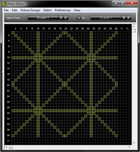
The DMX Map is one of three view modes that are available for the Patch Editor.
| ▪ | Voxel Map - Is the default view mode in order to work with the Patch Editor and the Patch. |
| ▪ | DVI Map - Is only relevant when working with DVI fixtures. Learn more »DVI Patch |
| ▪ | DMX Map - Allows you to view the Patch with regards to occupied and used DMX channels. |
| ▪ | To display DMX Channel mode, click DMX Map [menu View > DMX Map] [Keyboard shortcut: F7] |
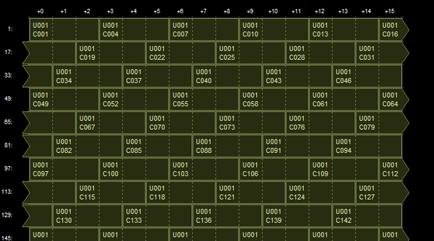
| ▪ | The DMX Map: - Is a separate view mode. But it is not independent from the Voxel Map. If you change something here, the corresponding settings will also change in the Voxel Map. - Shows all 512 DMX channels per DMX universe. - Shows the fixtures not based on their pixel/voxel count, but on the DMX channels they use. - Shows 16 DMX addresses per row. If a fixtures uses DMX channels that are located on several rows, the Patch Editor will display such a fixture with the help of a split arrow. - Is another way to work with DMX fixtures. It will be empty if you are only using DVI fixtures. - Can be used to work with DMX fixtures. A lot of the work-flows of the Voxel Map will work here as well. |
| ▪ | In order to work in a specific DMX universe, select the particular DMX Universe first. |
![]()
Overview
While the Patch Editor can only load and activate 1 Patch at a time, it allows you to merge Patches together.
That means you can combine separate Patch files into one Patch file.
| ▪ | The Patch Editor allows you to merge 2 Patches in one procedure. |
| ▪ | By repeating the procedure, you can merge more than 2 Patches. |
Merging several Patches can be useful, for example, when:
| ▪ | Working on a large LED installation and first creating and testing the Patch for each section separately. |
| ▪ | Having different team members create different parts of an overall Patch. |
| ▪ | Wanting to join two separate LED projects into one larger project later. |
Step-By-Step Instructions
1] Create Your Patches
| ▪ | In order to merge two Patches, the different Patches need to be ready and available first. |
| ▪ | Make sure to have all Patch files saved and available in one location, such as the hard drive of your computer. |
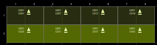
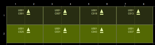
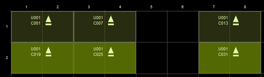
Patch 1 Example |
Patch 2 Example |
|
|


2] Load Patch 1
| ▪ | Load Patch 1 in the Patch Editor [Preferences > Patch Editor... > File > Open Patch...]. |
| ▪ | Or load Patch 1 as part of a MADRIX Setup [File > Open Setup...]. |
3] Activate The Merge Patches Feature
| ▪ | Go to Preferences > Patch Editor... > File > Merge Patches... |
| ▪ | Select Patch 2 from its stored location, such as the hard drive of your computer. |
| ▪ | A new window will open. |

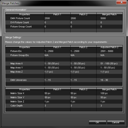
4] Adjust The Settings
| ▪ | The Merge Patches windows provides information about Patch 1 and Patch 2 and it requires you to adjust several settings in order that both Patches are merged according to your requirements. |
| ▪ | See the following table for more information: |
General Information |
|||
Properties |
Patch 1 |
Patch 2 |
Merged Patch |
DMX Fixture Count |
Shows the total number of DMX fixtures included in Patch 1. |
Shows the total number of DMX fixtures included in Patch 2. |
Shows the total number of DMX fixtures that will be included when the Patches are merged into one Patch. |
DVI Fixture Count |
Shows the total number of DVI fixtures included in Patch 1. |
Shows the total number of DVI fixtures included in Patch 2. |
Shows the total number of DVI fixtures that will be included when the Patches are merged into one Patch. |
Fixture Group Count |
Shows the total number of fixture groups in Patch 1. |
Shows the total number of fixture groups in Patch 2. |
Shows the total number of fixture groups that will be included when the Patches are merged into one Patch. |
Merge Settings |
|||
Properties |
Patch 1 |
Patch 2 |
Adjusted Patch 2 |
Fixture IDs |
Shows the unique identifiers for fixtures included in Patch 1. |
Shows the unique identifiers for fixtures included in Patch 2. |
- Since all Fixture IDs need to be unique, the settings for Patch 2 need to be adjusted here. |
Fixture Group IDs |
Shows the unique identifiers for fixture groups included in Patch 1. |
Shows the unique identifiers for fixture groups included in Patch 2. |
- Since all Fixture Group IDs need to be unique, the settings for Patch 2 need to be adjusted here. |
|
|
|
|
Map Area X |
Shows where fixtures are mapped in Patch 1 along the X-axis (e.g., position |
Shows where fixtures are mapped in Patch 2 along the X-axis (e.g., position |
- Defines the adjusted position of Patch 2 in X. |
Map Area Y |
Shows where fixtures are mapped in Patch 1 along the Y-axis (e.g., position |
Shows where fixtures are mapped in Patch 2 along the Y-axis (e.g., position |
- Defines the adjusted position of Patch 2 in Y. |
Map Area Z |
Shows where fixtures are mapped in Patch 1 along the Z-axis (e.g., position 1) and how many pixels are mapped in Z in total (e.g., 1 px). |
Shows where fixtures are mapped in Patch 2 along the Z-axis (e.g., position 1) and how many pixels are mapped in Z in total (e.g., 1 px). |
- Defines the adjusted position of Patch 2 in Z. |
|
|
|
|
DMX Universes |
Shows which DMX universes are used in Patch 1. |
Shows which DMX universes are used in Patch 2. |
- Defines the adjusted DMX universes for Patch 2. |
Properties |
Patch 1 |
Patch 2 |
Merged Patch |
Matrix Size X |
Shows the total number of DMX fixtures included in Patch 1. |
Shows the total number of DMX fixtures included in Patch 2. |
- Defines the Matrix Size in X that will be set when the Patches are merged into one Patch. |
Matrix Size Y |
Shows the total number of DVI fixtures included in Patch 1. |
Shows the total number of DVI fixtures included in Patch 2. |
- Defines the Matrix Size in Y that will be set when the Patches are merged into one Patch. |
Matrix Size Z |
Shows the total number of fixture groups in Patch 1. |
Shows the total number of fixture groups in Patch 2. |
- Defines the Matrix Size in Z that will be set when the Patches are merged into one Patch. |
Color Depth |
Shows the maximum color depth as defined in Patch 1. |
Shows the maximum color depth as defined in Patch 2. |
- Defines the color depth that will be set when the Patches are merged into one Patch. |
| ▪ | Please set up all settings of the column Adjusted Patch 2 as required and confirm with OK |
| ▪ | You can abort the process at any time with Cancel |
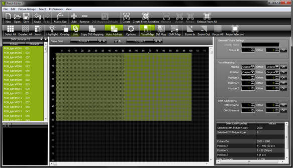
5] Result
| ▪ | As a result of the Merge Patches procedure, you will now have created 1 Patch out of 2 Patches. |
| ▪ | Overlapping will be activated in the Patch Editor automatically if needed. |
| ▪ | The Workspace of the Patch Editor will be extended automatically if needed. |
| ▪ | All imported fixtures of Patch 2 will be automatically selected for you after the procedure. |
| ▪ | You can use Undo or Redo to rewind the procedure or apply it again after a rewinding. |
| ▪ | Make sure to save your Patch or MADRIX Setup afterwards! |
Merge Settings Result Example |
|
Merged Patch Result Example |
|
Make sure to save your MADRIX Setup file after the configuration process.
You may also save and/or export the Patch file [of the file type *.mpz or *.mpx] separately. In the Patch Editor, go to File > Save Patch As...