This topic includes:
SCE Capture allows you to use any video signal of capture devices in MADRIX for live video feeds, such as installed webcams or TV-cards. Such devices need to provide the required Windows driver.
| ▪ | Several capture devices can be used at the same time. For every single Layer a different capture device or the same capture device can be utilized. |
| ▪ | If your device offers the correct drivers and is recognized in Windows as a capture device, MADRIX will also have access to the device. |
[In MADRIX 2, SCE Capture was part of SCE Video.]
|
|
 Default Settings |
 Customized Example |
| ▪ | Various buttons and controls have universal functions. They are available for each MADRIX Effect / Layer. Learn more »Effect Areas [Left/Right] Learn more »Layers |
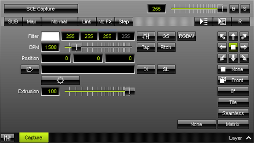
This MADRIX Effect uses the following, individual controls:
| ▪ | Filter - Defines a filter color. The default color is White. - GS - Activates grayscale mode to show the input only in gray shades. The Filter is independent of this mode. - RGBW - Converts the input into RGBW. This is useful when using RGBW fixtures to convert from the standard RGB color values of the input. If the option is disabled when using RGBW fixtures, the input will appear darker since the White channel is not used. The W color channel of the Filter only works if RGBW is activated. Learn more »Using Colors And Intensity |
| ▪ | BPM - Defines the speed [when using a direction/movement]. The default value is 1500. Valid values range from 0 to 9999. Learn more »Using BPM Control |
| ▪ | Position - Defines the position of the object in X, Y, and Z [in %]. The default values are 0, 0, 0. Valid values range from -1000 to 1000. |
| ▪ | Extrusion - Adds depth to the input; i.e. duplicates the input image [in % of the Matrix Size]. This is mainly relevant for 3D. The default value is 100. Valid values range from 0.01 to 100. |
|
Open - Allows you to connect a capture device. A new window opens for you to select your device. First, select the device. Second, click OK. |
|
Deinterlace Mode - Allows you to choose from several Deinterlace Modes. [Is available when a capture device has been opened and connected.] Often digital cameras, digital broadcasting, or digital filming is done via interlacing. In order to get 25 frames per seconds, 50 pictures are shot and merged/mixed with one another. You receive 25 odd frames [frame set 1] and 25 even frames [frame set 2] that contain different picture information [alternating pixel lines]. In order to get an undisturbed picture, proper deinterlacing is necessary. None - Deactivates deinterlacing. Bob - Uses one set of 25 frames [even or odd] and copies missing information from the pictures provided. Pixel lines are copied to create a full image. Activate Top Field First in order to choose odd frames to be processed. Bob Linear - This is the recommended deinterlace mode. It uses one set of 25 frames, but builds an average for the missing pixel lines. Activate Top Field First in order to choose odd frames to be processed. Blend - Renders an average image from frame set 1 and frame set 2. Discard - Simply dismisses missing information. Thereby, pixel lines are excluded. This results in half of the original resolution for the final image. Activate Top Field First in order to choose odd frames to be processed. |
|
Slices - Is a way to bring 2D content to 3D LED matrices by slicing the content into different parts and applying each slice to X-levels, Y-levels, or Z-levels as required. Learn more Slices |
|
Configuration - Allows you to configure the connected device further if such configuration is provided by the device and its driver. [Is available when a capture device has been opened and connected.] |
|
Filtering - Defines how input is processed and displayed. Mainly affects the visual outcome when the input is scaled up or down [e.g., when choosing a different mode for Stretching / Aspect Ratio]. Choose from 2 different modes. The default setting is None. |
|
Direction - Allows you to choose the direction. This includes all directions for 2D and 3D mode. The default value is None. |
|
Look-At Type - Allows you to choose from which side you want to look at the effect. This is mainly relevant for 3D. The default value is Front. Learn more »Using Directions |
|
Rotation - Allows you to rotate the input [0°, 90°, 180°, 270°]. The default value is 0. |
|
Tile - Allows you to tile and duplicate the input and thereby generating patterns. |
|
Seamless - Activates or deactivates a continuous stream of the input image. MADRIX will automatically display the input image again to create a continuous display. |
|
Stretching / Aspect Ratio - Allows you to choose the aspect ratio of the input. The default value is Matrix. None - Disables stretching. Matrix - Stretches to the current aspect ratio of the virtual LED matrix. Original - Stretches to the original aspect ratio of the source. 4:3 - Applies a 4:3 aspect ratio. 16:9 - Applies a 16:9 aspect ratio. |

Restoring The Default Settings
|
Restore Default Layer Settings - Restores the default settings of the Layer. |
![]() SL - Calls up Slice Settings
SL - Calls up Slice Settings
| ▪ | Slice Settings - Is a way to bring 2D content to 3D LED matrices by slicing the content into different parts and applying each slice to X-levels, Y-levels, or Z-levels as required. [You will get the most benefit out of this feature when using content that are made up of different parts and are especially created for this area of application.] Example: Your virtual LED matrix is 10 x 8 x 4. Now, you have prepared a video feed and want to display it not only on the first Z-level or use Extrude, but on all 4 Z-levels. Then, you would let MADRIX create 4 slices. |
| ▪ | Slice Type - Defines the 3D orientation of how slices are applied to your LED matrix. - X-Slices - Uses slices to fill the LED matrix; always starting from left to right. - Y-Slices - Uses slices to fill the LED matrix; always starting from top to bottom. - Z-Slices - Uses slices to fill the LED matrix; always starting from front to back. |
| ▪ | Slice Order - Defines how your source content is processed. - Left To Right - MADRIX slices the content starting left. [The first, left slice will then be applied to the left for X-Slices, to the top for Y-Slices, and to the front for Z-Slices.] - Right To Left - MADRIX slices the content starting right. [The first, right slice will then be applied to the left for X-Slices, to the top for Y-Slices, and to the front for Z-Slices.] - Top To Bottom - MADRIX slices the content starting top. [The first, top slice will then be applied to the left for X-Slices, to the top for Y-Slices, and to the front for Z-Slices.] - Bottom To Top - MADRIX slices the content starting bottom. [The first, bottom slice will then be applied to the left for X-Slices, to the top for Y-Slices, and to the front for Z-Slices.] |
| ▪ | Slice Count - Defines in how many slices the content is divided. A value of 1 means that no slices are created and that the video feed is used as one. [A value of 4, for example, will create 4 slices that each make up 25% of the source content.] |
| ▪ | The settings with the highest performance are Z-Slices and Top To Bottom |
| ▪ | Confirm with OK, reset to default settings via Default, or abort the process using Cancel |
| ▪ | Learn more »SCE Image |